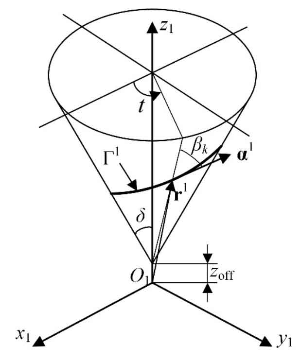
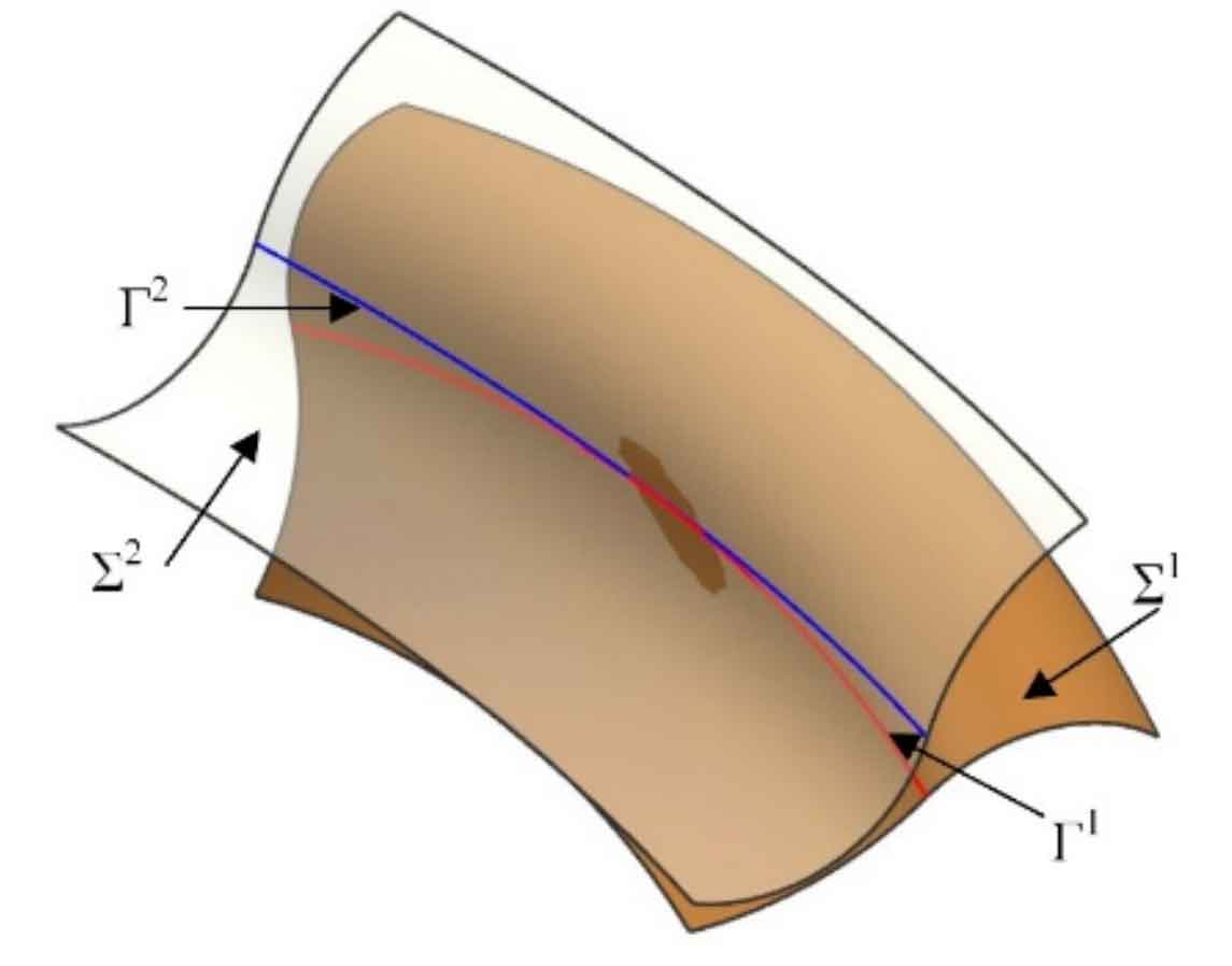
Based on the design process, the equiangular spiral bevel gear with discontinuous pure rolling contact can be designed. To change the equiangular spiral bevel gear into discontinuous pure rolling contact, only Γ 1 add a displacement along its rotation axis, as shown in Figure 1. At this time, under S1, Γ 1 can be expressed as follows:
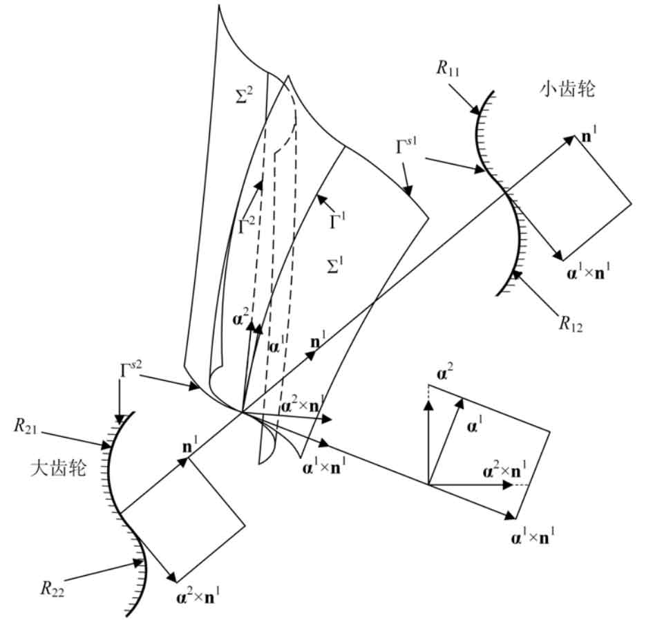
When Zoff = 0, Γ 1 satisfies the continuous pure rolling contact condition. When Zoff ≠ 0, then Γ 1. The continuous pure rolling contact condition is not satisfied. According to the process, the formula and parameters can be obtained Γ Conjugate curve of 1. As before, you can still use the normal section curve Γ S1 and Γ S2 is designed as a double segment arc, as shown in Figure 2. Make kn12 = 1 / R11 and kn22 = 1 / R21 at the top of pinion. Make kn12 = – 1 / R12 and kn22 = – 1 / R22 at the tooth root of the pinion.
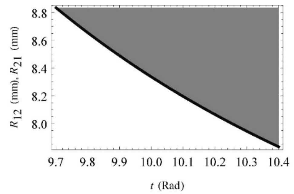
When Zoff = 0, Γ 1 if the continuous pure rolling contact condition of conjugate curve bevel gear is satisfied, the curvature condition obtained at this time should be consistent. Therefore, if R11 = R22 = 6mm, the value range of R12 and R21 can be obtained from the design process, as shown in Figure 3. The value range is consistent with that obtained in Chapter 3, which shows that the curvature limit condition obtained is still applicable to continuous pure rolling contact bevel gears.
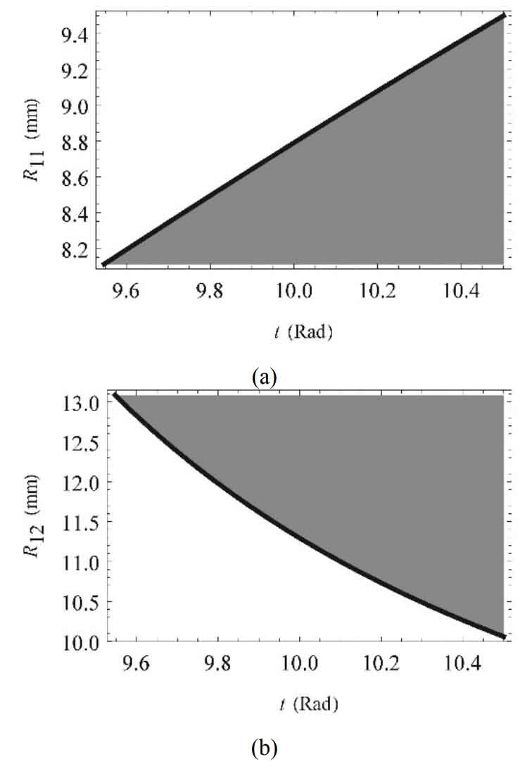
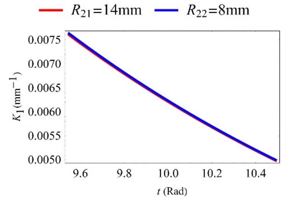
In order to verify whether the model is applicable to non pure rolling contact conjugate curve bevel gears, Zoff = 1 is set first. At this point, Γ 1. The continuous pure rolling contact condition is not satisfied. If shilling R21 = 14mm and R22 = 8mm, the value of K1 can be obtained, as shown in Figure 4. It can be seen that K1 ≥ 0 in the inequality group has been satisfied. After R21 and R22 are determined, the value range of R11 and R12 can be obtained from the inequality conditions, as shown in Figure 5. Finally, set R11 = 8mm and R12 = 14mm.
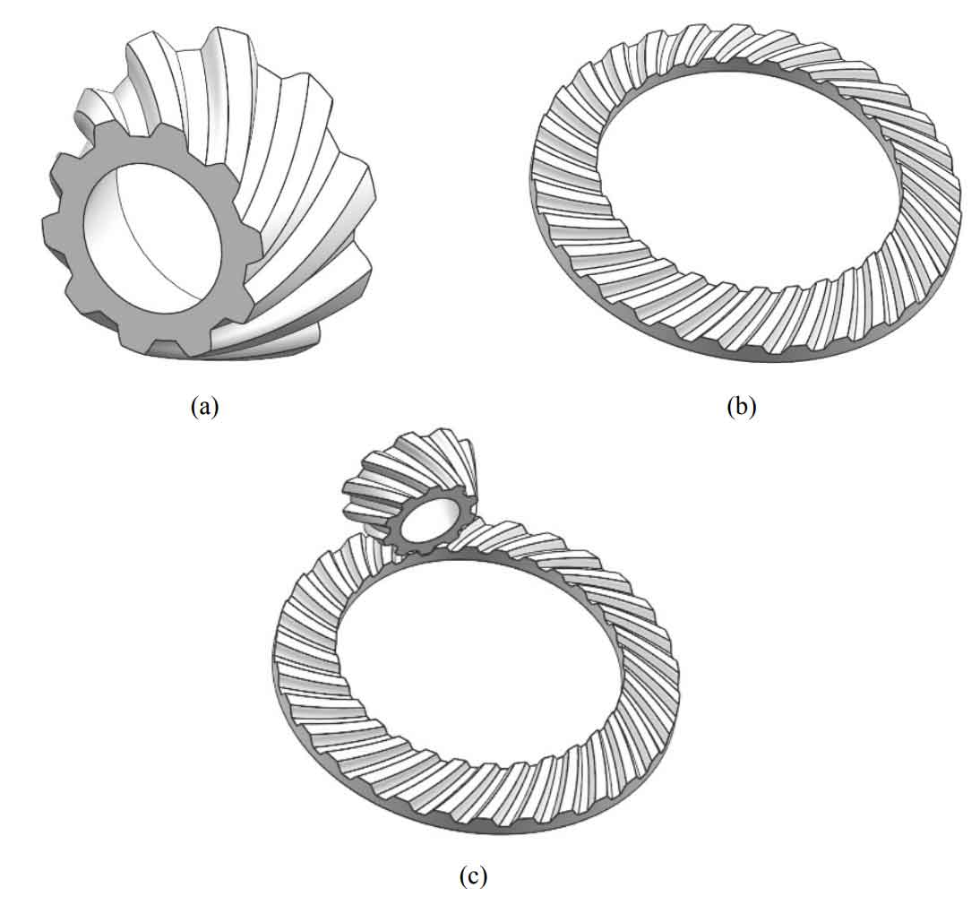
After R11, R12, R21 and R22 are determined, the tooth surface can be obtained according to the method Σ 1 and Σ 2, as shown in Figure 6. Each tooth surface consists of 200 × 40 points. The tooth surface on the other side can be designed in the same way. Then, according to the geometric design parameters, the pinion and big gear models can be generated, as shown in Figure 7.