
The equivalent stress distribution diagram can clearly show the equivalent stress distribution in the bevel gear blank, so that the analysts can quickly determine the area with the maximum equivalent stress and the maximum value of the equivalent stress in the bevel gear blank, so as to predict the location and type of defects.
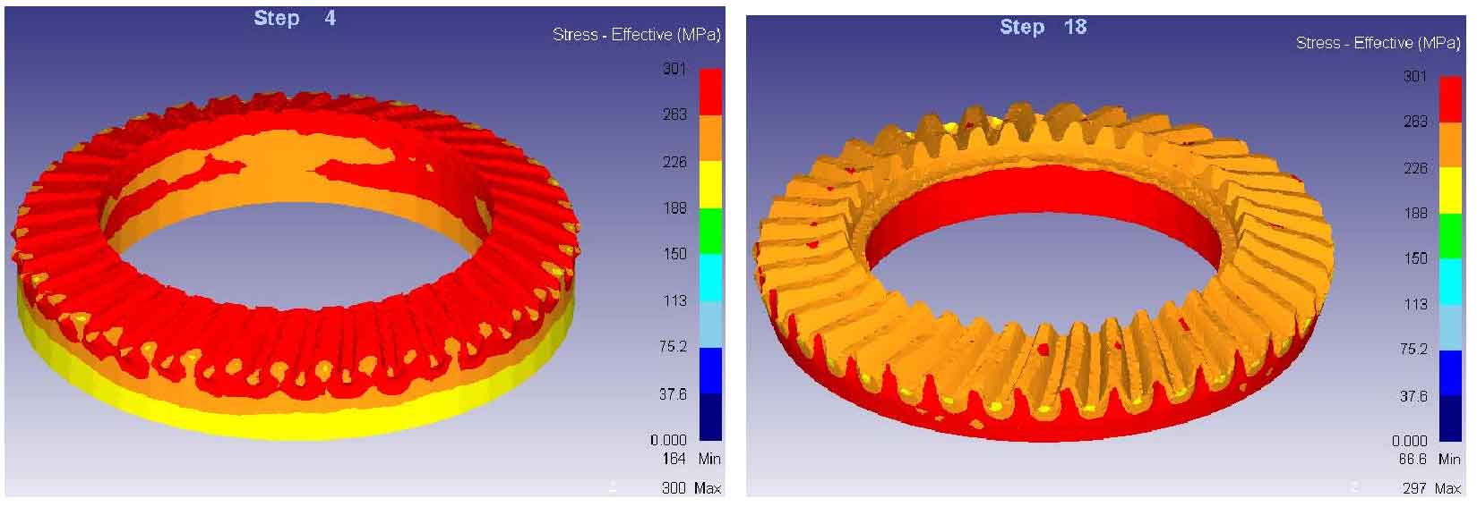
(b) Equivalent stress distribution with a stroke of 11 mm
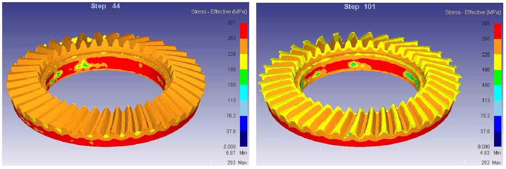
(d) Equivalent stress distribution diagram of final step
The figure shows the equivalent stress distribution diagram of different strokes in the warm precision forging process, in which figure (a) is the equivalent stress distribution diagram when the stroke is 2.7 mm. It can be seen from the figure that as the upper die starts to move downward, the part with the largest equivalent stress is mainly concentrated at the place where the upper die contacts the bevel gear blank, while the equivalent stress in the lower half of the bevel gear blank is small; Figure (b) is the equivalent stress distribution diagram when the stroke is 11 mm. From figure (a) to figure (b), the main deformation is upsetting deformation. According to the stress distribution diagram, the equivalent stress of the tooth profile is relatively small, while the equivalent stress at the bottom of the bevel gear is relatively large; Figure (c) is the equivalent stress distribution diagram when the stroke is 12.3 mm. From figure (b) to figure (c), the main deformation is that the metal flows into the cavity of the tooth shape and fills the whole cavity to form the tooth shape of the bevel gear. It can be seen that the tooth top part becomes more flat. In this process, the equivalent stress of the tooth shape part continues to decrease and become more uniform; Figure (d) is the equivalent stress distribution diagram of the final step. The main deformation from figure (c) to figure (d) is the formation of flash. It can be seen from the equivalent stress distribution diagram that the equivalent stress of the tooth profile continues to decrease in this process, while the equivalent stress under the bevel gear remains basically unchanged.
For the whole forming process, the equivalent stress of the upper part of the bevel gear, that is, the part of the tooth profile, begins to be large, and then decreases gradually in the whole process; The equivalent stress of the lower part of the bevel gear is very small at the beginning. With the downward movement of the upper die, the equivalent stress gradually increases and remains basically unchanged after reaching a certain value. The maximum equivalent stress in the whole forming process is only 301 MPa, which is relatively small, which proves that warm precision forging of automobile rear axle driven bevel gear is feasible and practical.