
The rotary vector reducer stands as a cornerstone of modern industrial robotics, prized for its exceptional load-bearing capacity, high reduction ratio, and, most critically, its superior transmission accuracy. To meet the stringent demands of precision automation, the allowable transmission rotation angle error for these devices is typically no greater than 1 arcminute. Achieving this level of precision is a formidable challenge, as the cumulative effect of minute errors originating from the manufacturing and assembly of individual components can severely degrade the overall system performance. Among these, the second-stage reduction part—comprising the cycloid gears, the crankshafts, and the output mechanism—is identified as the most significant contributor to the total transmission error. The geometric imperfections in these components, known as original errors, directly disrupt the ideal motion transfer. This analysis focuses on modeling the interaction between these three key elements as a four-bar linkage mechanism. This model elegantly captures their kinematic relationship and establishes a direct functional connection between the input and output rotation angles of the second stage. By analyzing the error propagation within this four-bar framework, we can derive the specific influence laws of various original errors on transmission accuracy. The ultimate goal is to formulate scientifically-grounded deviation tolerance standards and control methodologies, thereby providing valuable theoretical guidance for the manufacturing and assembly processes of high-precision rotary vector reducers.
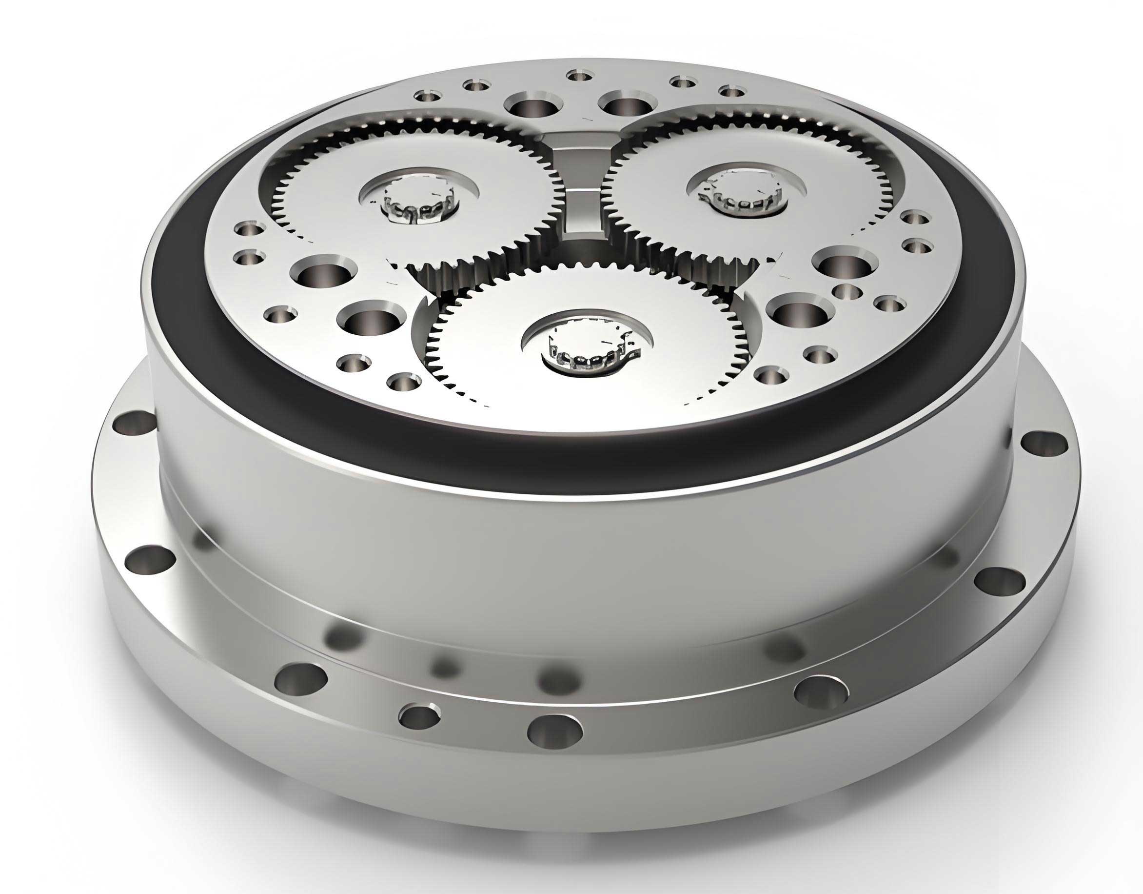
The specific type of rotary vector reducer under examination in this discussion is the RV-40E model, which features a two-stage reduction system. The first stage consists of an involute spur gear train, while the second stage employs a double-cycloid pin-wheel transmission mechanism. The fundamental technical parameters for the RV-40E are summarized in the table below.
| Parameter Name | Value |
|---|---|
| Pin Gear Center Circle Diameter, \(d_p\) (mm) | 128 |
| Pin Diameter, \(D_{rp}\) (mm) | 6 |
| Number of Cycloid Gear Teeth, \(z_c\) | 39 |
| Center Gear Teeth, \(z_1\) | 10 |
| Planet Gear Teeth, \(z_2\) | 26 |
| Pin Gear Teeth, \(z_p\) | 40 |
| Crankshaft Eccentricity, \(e\) (mm) | 1.3 |
| Motor Input Speed, \(n\) (r/min) | 525 |
Establishment of the Four-Bar Linkage Model
The core innovation of this analysis lies in simplifying the kinematic chain of the second-stage reduction part into an equivalent planar four-bar linkage. In this abstraction, each crankshaft’s eccentric portion is represented by two crank arms, \(l_1\) and \(l_3\). The center distance between the crankshaft bearing holes on the cycloid gear corresponds to the coupler link, \(l_2\). Finally, the center distance between the crankshaft bearing holes on the output mechanism (often the planet carrier) is represented by the ground link, \(l_4\). Under ideal, error-free conditions, these links form a perfect parallelogram \(O_1P_iP_jO_2\), ensuring synchronized and precise motion transfer. However, the introduction of original errors—such as eccentricity errors in the crankshafts, positional errors in the cycloid gear’s holes, and errors in the output mechanism’s holes—alters the lengths and angular orientations of these links, breaking the perfect parallelogram and leading to the distorted configuration \(O_1P’_iP’_jO’_2\).
The kinematic closure equation for the four-bar linkage, accounting for deviations in link lengths and angles, is given by the vector sum:
$$ \vec{l’}_1 + \vec{l’}_2 – \vec{l’}_3 = \vec{l’}_4 $$
where \(l’_i = l_i + \Delta l_i\) represents the actual length of link \(i\), and its orientation is \(\beta’_i = \beta_i + \Delta \beta_i\). Projecting this vector equation onto the x and y axes yields the following scalar equations:
$$ (l_1 + \Delta l_1) \cos \beta’_1 + (l_2 + \Delta l_2) \cos \beta’_2 = (l_3 + \Delta l_3) \cos \beta’_3 + (l_4 + \Delta l_4) \cos \beta’_4 $$
$$ (l_1 + \Delta l_1) \sin \beta’_1 + (l_2 + \Delta l_2) \sin \beta’_2 = (l_3 + \Delta l_3) \sin \beta’_3 + (l_4 + \Delta l_4) \sin \beta’_4 $$
Furthermore, the presence of radial clearance in the bearing connections (the revolute joints) introduces additional displacement at the hinge points. The displacement vector for a joint can be modeled as:
$$ \Delta \vec{p} = \vec{P}_i\vec{P’}_i = \Delta_p \vec{f}_p $$
where \(\Delta_p\) is the radial clearance and \(\vec{f}_p\) is the unit vector in the direction of relative displacement between the connected links.
To simplify the analysis for the case where the output mechanism’s positional error is initially neglected (making \(\beta_2 \approx 0\)), we can use small-angle approximations for \(\Delta \beta_2\): \(\sin \beta’_2 \approx \beta’_2\) and \(\cos \beta’_2 \approx 1 – (\beta’_2)^2/2\). Substituting these into the projected equations and rearranging terms leads to a quadratic equation in \(\beta’_2\):
$$ a(\beta’_2)^2 + b\beta’_2 + c = 0 $$
where the coefficients are functions of the deviated link lengths and the input angle \(\beta’_1\):
$$ a = l’_2 l’_4 – l’_1 l’_2 \cos \beta’_1 $$
$$ b = 2 l’_1 l’_2 \sin \beta’_1 $$
$$ c = (l’_1)^2 + (l’_2)^2 + (l’_4)^2 – (l’_3)^2 – 2l’_1 l’_4 \cos \beta’_1 + 2l’_1 l’_2 \cos \beta’_1 – 2l’_2 l’_4 $$
Solving this quadratic equation for \(\beta’_2\) for a given input angle \(\beta’_1\) and set of errors \(\Delta l_i\) allows us to compute the resulting output angle error, which is directly related to the transmission error of the rotary vector reducer.
Analysis of Crankshaft Eccentricity Error
The eccentricity of the crankshaft is a fundamental design parameter in a rotary vector reducer, dictating the amplitude of the cycloidal motion. Any deviation from its nominal value, \(\Delta e\), directly translates into an error in the effective lengths of the crank links \(l_1\) and \(l_3\) in our four-bar model. In the rigid-body error analysis (neglecting deformations under load), bearing clearances \(\Delta_{pi}\) and \(\Delta_{pj}\) cause the centers of the joints at \(P_i\) and \(P_j\) to shift, altering the instantaneous positions of \(l_1\), \(l_2\), and \(l_3\), while \(l_4\) remains fixed. The mechanism deforms from the ideal parallelogram \(O_1P_iP_jO_2\) to \(O_1P’_iP’_jO_2\).
However, a complete accuracy assessment for a rotary vector reducer must consider elastic deformations under operational loads. The forces acting on the cycloid gear from the meshing with pin wheels are transferred to the crankshafts. These forces, resolved into tangential and radial components (\(F^t\) and \(F^r\)), induce elastic deflections at the bearing connections. Let \(l_{11}\) and \(l_{33}\) represent these elastic displacement vectors at the connections of cranks \(l’_1\) and \(l’_3\), respectively. The effective crank lengths under load, \(l”_1\) and \(l”_3\), are then found from the triangles formed by the rigid-error crank and the elastic displacement vector:
$$ l”_1 = \sqrt{ (l’_1)^2 + (l_{11})^2 – 2 (l’_1 \cdot l_{11}) \cos \theta_1 } $$
$$ l”_3 = \sqrt{ (l’_3)^2 + (l_{33})^2 – 2 (l’_3 \cdot l_{33}) \cos \theta_3 } $$
Here, \(\theta_1\) and \(\theta_3\) are the angles between the rigid-error crank vector and the corresponding elastic displacement vector. Analysis indicates that the maximum rigid error occurs when the input angle \(\beta’_1 = 90^\circ\). For the RV-40E under typical load, with specific force values, the angles can be calculated as:
$$ \theta_1 = 90^\circ + \arctan\left( \frac{-F^t_{34′}}{F^r_{34}} \right) $$
$$ \theta_3 = 90^\circ – \arctan\left( \frac{F^t_{34}}{F^r_{34}} \right) $$
Numerical simulation for an eccentricity error range of \([-0.1 \, \text{mm}, +0.1 \, \text{mm}]\) shows that the rigid transmission error varies approximately between \([0.0333^\circ, 0.0389^\circ]\), while the elastic error is slightly larger, ranging from \([0.0335^\circ, 0.0390^\circ]\). Crucially, the trend reveals that when both crankshafts have a negative bias in their eccentricity error (i.e., the eccentricity is smaller than nominal), the output rotation accuracy of the rotary vector reducer improves. Conversely, a positive bias (larger than nominal eccentricity) degrades accuracy.
Analysis of Cycloid Gear Crankshaft Hole Error
Manufacturing inaccuracies in the position of the crankshaft bearing holes on the cycloid gear constitute another critical source of error. In the four-bar model, this error primarily affects the coupler link \(l_2\), which represents the distance between the two hole centers. A positional or eccentricity error in these holes changes the actual length \(l’_2\) and its orientation \(\beta’_2\). In the rigid analysis, with bearing clearances, links \(l_1\) and \(l_3\) change only in orientation, \(l_2\) changes in both length and orientation, and \(l_4\) is fixed. Under load, elastic displacements \(l_{11}\) and \(l_{33}\) again modify the effective crank lengths to \(l”_1\) and \(l”_3\) as per the equations given in the previous section.
The analysis yields an interesting and important result. For the cycloid gear hole error varying within \([-0.1 \, \text{mm}, +0.1 \, \text{mm}]\), the rigid error range is \([0.036058^\circ, 0.036111^\circ]\) and the elastic error range is \([0.03618^\circ, 0.03624^\circ]\). The key finding is that the transmission accuracy shows a slight improvement whether the error shifts towards the positive or negative bias, compared to the nominal zero-error case. This implies that an error in the cycloid gear holes can, in certain configurations, partially compensate for other inherent errors in the system, such as those from the crankshafts. Therefore, from a manufacturing tolerance perspective, the hole positions on the cycloid gear for a rotary vector reducer can be allowed a symmetric tolerance band without necessarily degrading performance; in fact, it may be strategically useful.
Analysis of Output Mechanism Crankshaft Hole Error
The final element in the chain is the output mechanism, which houses the opposite ends of the crankshafts. Errors in the position of its bearing holes directly affect the ground link \(l_4\) of the four-bar model. In the rigid-error state, this changes the length \(l’_4\) while its orientation typically remains fixed (aligned with the output axis). Links \(l_1\), \(l_2\), and \(l_3\) undergo changes in orientation due to bearing play. The elastic error analysis follows the same pattern, incorporating deflections \(l_{11}\) and \(l_{33}\).
Simulation for an output hole error in the range \([-0.1 \, \text{mm}, +0.1 \, \text{mm}]\) shows a rigid error range of \([0.036008^\circ, 0.036123^\circ]\) and a more significant elastic error range of \([0.038588^\circ, 0.038706^\circ]\). The relationship between error bias and accuracy is distinct: as the error moves towards a negative bias, accuracy first decreases then shows a minor recovery. In stark contrast, a movement towards a positive bias (larger center distance) leads to a substantial increase in transmission accuracy for the rotary vector reducer. This provides a clear directive for manufacturing: the bore centers on the output mechanism should be biased towards the upper limit of the tolerance band.
The following table summarizes the influence trends and design guidelines derived from the single-error analysis:
| Error Source | Mainly Affects Link | Accuracy Trend vs. Error Bias | Proposed Manufacturing Bias |
|---|---|---|---|
| Crankshaft Eccentricity | \(l_1, l_3\) (Cranks) | Improves with negative bias | Lower Limit (Smaller Eccentricity) |
| Cycloid Gear Holes | \(l_2\) (Coupler) | Improves slightly with both biases | Symmetric Tolerance Acceptable |
| Output Mechanism Holes | \(l_4\) (Ground) | Greatly improves with positive bias | Upper Limit (Larger Center Distance) |
Comprehensive Error Interaction Analysis
In a real rotary vector reducer, all error sources coexist and interact. Therefore, analyzing their combined effect is essential. The four-bar model is well-suited for this multi-variable analysis. By varying two error parameters simultaneously while solving the kinematic equations, we can generate sensitivity surfaces that show the combined output error.
1. Crankshaft & Cycloid Gear Hole Errors: The interaction between crankshaft eccentricity error (\(\Delta e\)) and cycloid gear hole error creates a convex, stepped surface. The lowest error (highest accuracy) region corresponds to negative crankshaft bias, consistent with the single-error analysis, while the cycloid hole error can vary within its range without drastic penalty. The combined rigid error range is \([0.0347^\circ, 0.0375^\circ]\), with elastic errors slightly higher at \([0.0355^\circ, 0.0383^\circ]\).
2. Crankshaft & Output Mechanism Hole Errors: The interaction between \(\Delta e\) and the output hole error also produces a convex surface. The high-accuracy region is clearly associated with negative crankshaft bias and positive output hole bias. The combined rigid and elastic error ranges are \([0.0346^\circ, 0.0375^\circ]\) and \([0.0354^\circ, 0.0383^\circ]\), respectively.
3. Cycloid Gear & Output Mechanism Hole Errors: This interaction yields a more complex surface with a concave central region and raised edges. The highest accuracy occurs under two extreme, opposite combinations: a) large positive cycloid hole error with large negative output hole error, and b) large negative cycloid hole error with large positive output hole error. Since the single-error analysis strongly recommends a positive bias for the output holes to enhance rotary vector reducer accuracy, the optimal practical combination from this pair is to select a negative bias for the cycloid gear holes alongside the positive bias for the output holes. The error ranges for this combination are \([0.0358^\circ, 0.0362^\circ]\) (rigid) and \([0.0384^\circ, 0.0387^\circ]\) (elastic).
| Error Combination | Key Finding for Optimal Accuracy | Rigid Error Range | Elastic Error Range |
|---|---|---|---|
| Crankshaft + Cycloid Holes | Prioritize negative crankshaft bias. | \([0.0347^\circ, 0.0375^\circ]\) | \([0.0355^\circ, 0.0383^\circ]\) |
| Crankshaft + Output Holes | Combine negative crankshaft and positive output hole bias. | \([0.0346^\circ, 0.0375^\circ]\) | \([0.0354^\circ, 0.0383^\circ]\) |
| Cycloid Holes + Output Holes | Combine negative cycloid hole and positive output hole bias. | \([0.0358^\circ, 0.0362^\circ]\) | \([0.0384^\circ, 0.0387^\circ]\) |
Conclusions and Design Implications
This systematic analysis using a four-bar linkage model has successfully elucidated the influence laws of key original errors on the transmission accuracy of a rotary vector reducer. The primary conclusions are as follows:
1. The transmission error is sensitive to the direction (bias) of component errors, not just their magnitude. For the RV-40E model, optimal accuracy is achieved when: crankshaft eccentricity errors are biased towards the lower limit (smaller eccentricity), cycloid gear crankshaft hole errors are biased towards the lower limit, and output mechanism crankshaft hole errors are biased towards the upper limit (larger center distance).
2. The strategic allocation of tolerances based on these bias recommendations can effectively improve the assembled accuracy of a rotary vector reducer without necessarily tightening individual manufacturing tolerances, which is a cost-effective strategy.
3. Bearing clearance plays a dual role. While it allows for the interaction and potential compensation of different geometric errors in the rigid state, it also contributes to the overall error. More importantly, the analysis consistently shows that the elastic transmission error (under load) is greater than the rigid error. This underscores the critical importance of controlling bearing clearance and enhancing the stiffness of the crankshaft-bearing connections to minimize elastic deflections.
4. The four-bar model provides a powerful and intuitive framework for analyzing the complex error interactions within the second stage of a rotary vector reducer. It transforms the problem of transmission accuracy into one of linkage kinematics, enabling clear visualization and calculation of how individual component imperfections propagate to affect the final output. This model serves as a valuable theoretical tool for guiding the precision design, manufacturing, and assembly of high-performance rotary vector reducers.