The workpiece coordinate system is established by taking the installation surface of the workpiece gear as the coordinate plane and the rotary axis of the gear as the axis (as shown in the figure). The zero point of the Zero 3 axis is the intersection of the Zero 3 axis and the gear mounting surface, and the positive point of the Zero 3 axis points to the gear pitch cone vertex.

When calculating the curvature of the tooth surface and the adjustment parameters of the machine tool, it is necessary to specify the calculation point on the tooth surface of the workpiece.
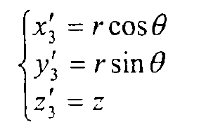
For this reason, a cylindrical coordinate system (Omurr, θ, z) is established, in which the z axis coincides with the zonal 3 axis, and θ is the positive coincidence of the 00:00 polar diameter and the xylene 3 axis.
Make the shaft section of the workpiece gear, and project the bevel gear teeth to the shaft section according to the angle θ direction. Because the tooth surface equation of spiral bevel gear can not be expressed by analytical expression, it is necessary to discretize the tooth surface. The mesh is divided along the tooth length direction and tooth height direction of the root cone on the gear tooth shaft profile, and the mesh density is selected according to the number and accuracy of the calculation points. Here, the gear is divided into 10 grids along the tooth length direction and 6 grids along the tooth height direction. Among them, the distance of the grid line along the tooth height direction is equal in the tooth length direction, while the angle between the grid line along the tooth length direction and the tooth root line is different, the innermost grid line coincides with the tooth root line, and the outermost grid line coincides with the tooth tip line. The angle between the middle wire and the root line varies uniformly from the inside to the outside.

The grid points are numbered as shown in the figure. If the root cone angle of the gear is δ f, the face cone angle is δ a, the root cone distance of the big end is Rfe, the tooth length is b, and the root height of the big end is he, then the coordinates of the point p (iForce j) numbered (iForce j) are as follows:
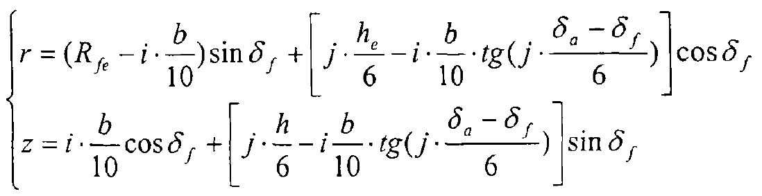
Converted to a Cartesian coordinate system, the coordinates are: