
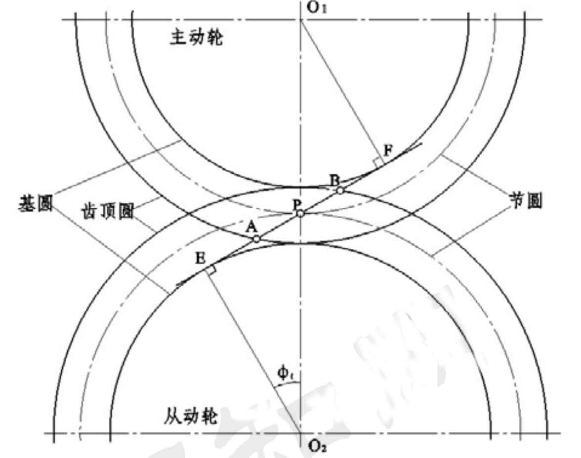
For helical gears, the whole coincidence degree is greater than 2, which means that at least 2 tooth pairs are engaged at the same time. Therefore, the operation of helical gears is much more stable than that of spur gears. The number of contact lines of helical gears also depends on the geometric parameters of helical gears, such as helix angle, axial coincidence degree, end face coincidence degree, etc. Figure 1 is the schematic diagram of helical gear meshing area and contact line. The width F of the meshing plane is formed by the joint action of the meshing line EF and the addendum circle of the driving and driven wheels. The expression is as follows:

Where:
Rα —— Top circle radius of driving gear (mm);
rα —— Radius of driven gear tooth top circle (mm);
R – pitch circle radius of driving wheel (mm);
r – pitch circle radius of driven wheel (mm);
αT — end face pressure angle (°).
In Figure 1, point P is the node, point E is the starting point of the meshing line, point F is the end point of the meshing line, and points a and B are the intersection of the meshing line and the addendum circle.
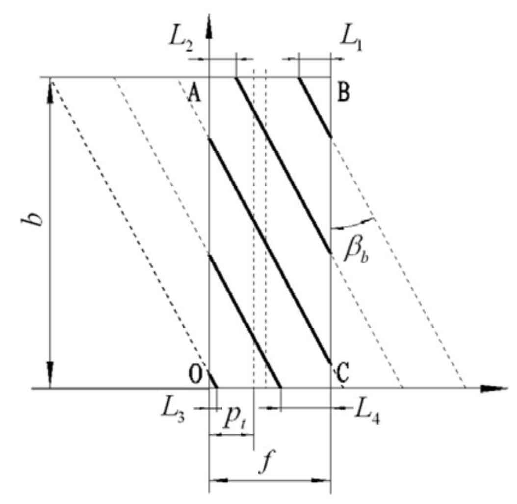
The length change of the contact line is shown in Figure 2. The length of the contact line gradually increases with the engagement of the helical gear, and then remains unchanged for a period of time, with the length gradually decreasing. The distance between two adjacent contact lines is one end tooth pitch Pt, and the axial and vertical distances of two adjacent contact lines are axial tooth pitch PA and vertical tooth pitch PN. It can be seen from the figure that the length of the contact line changes periodically with one end tooth pitch. Based on the relationship between the width ratio B F and 1 of the helical gear width and the meshing plane, three cases are considered as the shape criteria for determining the meshing plane, and the general calculation formula of the contact line is derived.