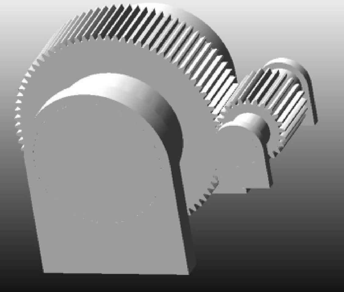
Contact force and angular acceleration are important parameters to test the effect of spur gear modification. Based on the parameters of the spur gears listed in the table, 3D models and meshing assembly models of standard spur gears, ISO maximum modification spur gears, and elastohydrodynamic friction pair stiffness maximum modification spur gears are established through Creo. They are imported into Adams through Parasolid files, and fixed pairs are applied to the spur gear support in Adams. Rotating pairs are applied to the spur gear shaft and support, and solid solid collision forces are applied between the spur gears, The complete Adams spur gear meshing virtual prototype model is obtained by applying rotational speed drive on the input shaft and load torque constraints on the output shaft, as shown in the figure.
| Parameter | Pinion | Wheel |
| Number of teeth | 25 | 80 |
| Modulus/mm | 8 | 8 |
| Pressure angle (/°) | 20 | 20 |
| Tooth width/mm | 200 | 200 |
| Materials, heat treatment | 20CrNiMo carburizing and quenching | 15CrNi6 carburizing and quenching |
| Tooth surface roughness/µm | 0.2 | 0.2 |
| Lubricant viscosity (/Pa · s) | 0.038 | 0.038 |
| Viscous pressure coefficient of lubricating oil/Pa^-1 | 2.2X10^-8 | 2.2X10^-8 |
| Speed (/r/min) | 1 500 | 468.75 |
| Input power/kW | 800 | 800 |
Use the Impact function to calculate the dynamic contact force on the tooth surface. During simulation, the collision index is taken as 1.5 and the damping coefficient is 30 N · s/mm. The breakdown depth at maximum damping is 0 1 mm。 The static friction coefficient is taken as 0.3, and the dynamic friction coefficient is taken as 0 1.
