According to the structural design of the new cutting tool, the key dimensions of the spiral bevel gear milling tool are calculated. According to the calculated parameters of spiral bevel gear, the adjustment angle of spiral bevel gear blank to be machined is 0 °. According to the design of the new gear milling tool in Chapter 3, the 0 ° intersection line between the hemispherical blade end face and the (q) plane when the blade rotates at high speed can be used as the tooth surface generation line for gear cutting, and the installation angle of the blade θ’ The value of is 0 °.
Next, the radius of the blade is solved. On the premise that the tool position q is equal to the blade radius R and the spiral angle of the spiral bevel gear is 30 °, the radius of the outer edge of the tool for machining concave tooth surface and the inner edge of the tool for machining convex tooth surface are equal, which are:
According to the formula in the design of the blade thickness at the end of the blade, the problem of the tooth surface generating line rolling from the base cone to the pitch cone can be solved φ And θ The values of the two are shown in the following expression:
The calculated φ And θ Value is substituted into the formula and simplified to obtain the following relationship:
For the angle between the tooth groove width at the base cone of the small end of the spiral bevel gear and the rotation axis in the formula—— α The value can be solved with the help of solve and eval functions in MATLAB. The solving functions are as follows:
The solution function can be used to obtain α The value is:
Since the base cone angle and root cone angle are equal, that is, the base cone coincides with the root cone, the tooth width at the root cone at the small end of spiral bevel gear is equal to that at the base cone. For the solution of the tooth slot width at the base cone, the φ= 0 θ= 0 and formula α The value of is substituted into the formula for solution.
According to the spiral bevel gear milling tool, the end thickness of the cutting edge must be less than the tooth groove width s at the tooth root of the small end of the spiral bevel gear. At the same time, in order to make the machining allowance of the convex and concave surfaces basically equal, the end thickness of the cutting edge is taken as l = s / 2 ≈ 3.
According to the geometric parameters of spiral bevel gear, the large end full tooth height h of spiral bevel gear to be machined can be obtained:
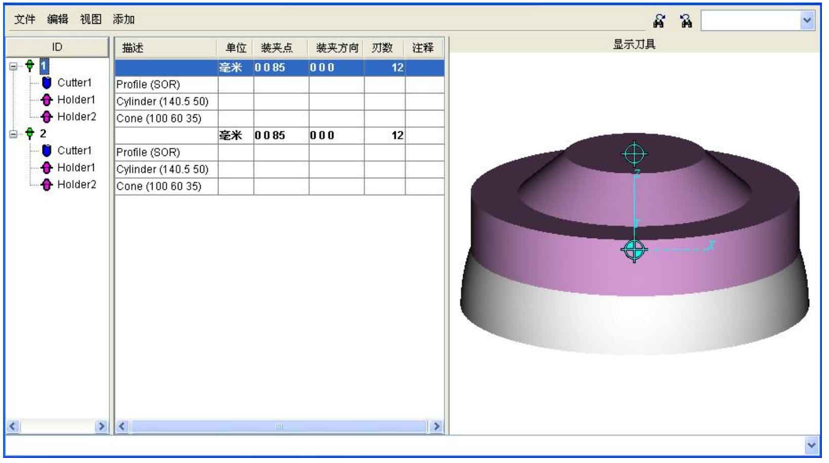
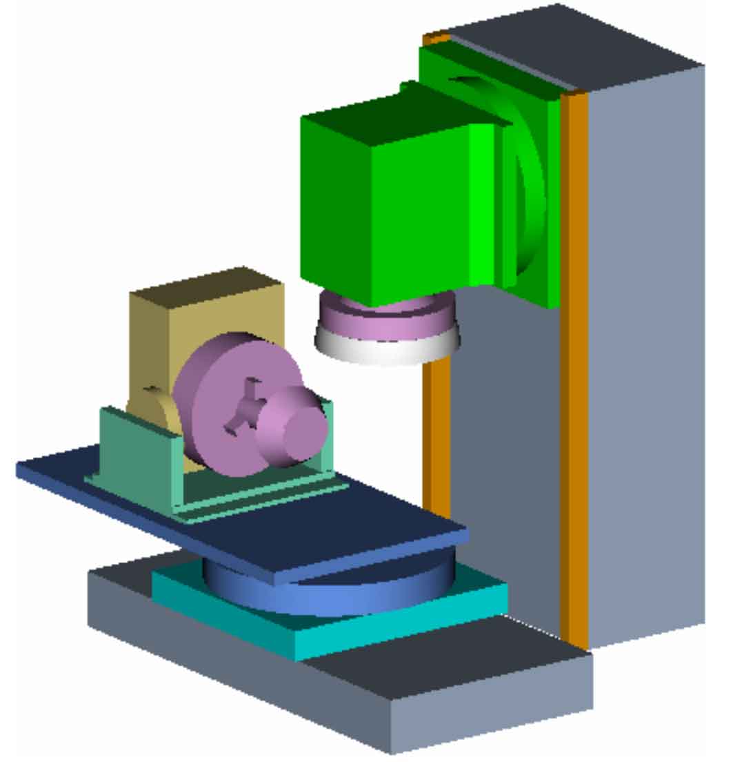
Then the total height of the designed gear milling tool blade must be greater than 15.104mm. According to the calculation and analysis of the above key parameters of the cutting edge, two new tools are built in VERICUT’s tool library: an outer edge milling cutter and an inner edge milling cutter. As VERICUT’s process of material removal machining simulation is actually a Boolean subtraction operation process, the gear cutting tool for simulation cannot be made the same as the actual tool, but must be made into a hemispherical milling cutter formed by the high-speed rotation of the blade in the machining process, so as to make the simulation result of gear cutting machining equivalent to the actual machining. The model of the new spiral bevel gear milling cutter is shown in Figure 1. Among them, cutter 1 is the outer edge milling cutter for machining the concave tooth surface of spiral bevel gear, and cutter 2 is the inner edge milling cutter for machining the convex tooth surface of spiral bevel gear. Select the center point of the upper end face of the tool handle – (0.085) as the clamping point of the tool and install it on the model of the gear cutting machine tool, as shown in Figure 2.