According to the stress analysis of the driven gear, the relative displacement xn of the two spiral bevel gears along the meshing line is:
Where, α N is the normal pressure angle; β M is the helix angle at the midpoint; δ 2 is the pitch cone angle of driven bevel gear; RP1 and RP2 are the meshing point radius of the main and driven wheels respectively; En (T) is the normal static transmission error of spiral bevel gear pair; Er is transmission error amplitude; E0 is the transmission error constant; Ω is the meshing angular frequency of spiral bevel gear pair; Φ Is the meshing phase angle of spiral bevel gear pair.
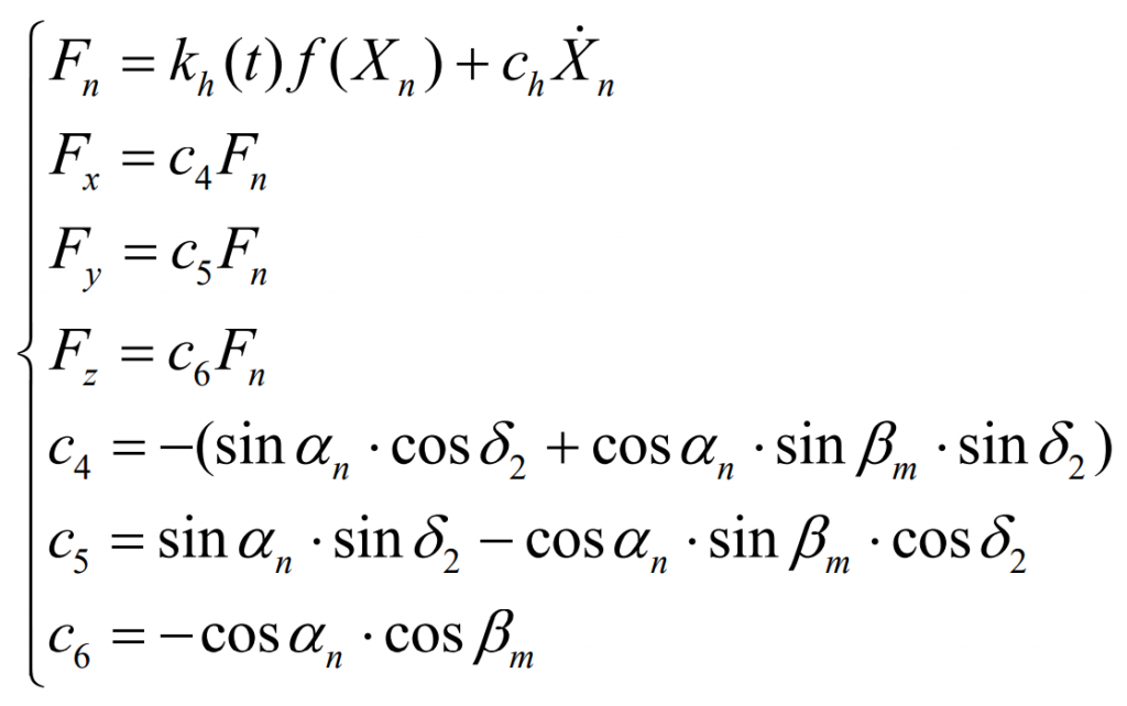
In the meshing process, the normal load on the driven spiral bevel gear pair and its component forces along each coordinate axis are respectively:
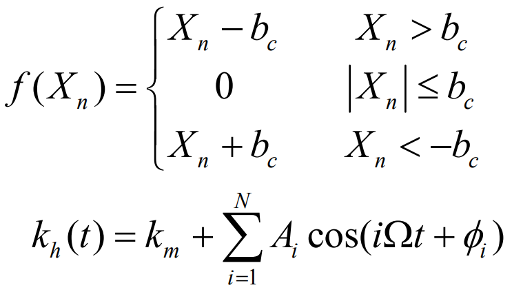
Where KH (T) is the time-varying meshing stiffness of spiral bevel gear pair; F (xn) is the tooth side clearance function; Ch is meshing damping. And:
Where BC is half of the normal average meshing clearance; Km is the average value of time-varying meshing stiffness; AI is the i-order amplitude of time-varying meshing stiffness; Φ I is the i-order phase angle of time-varying meshing stiffness.
The friction moment of the damping ring is:
Where N1 is the positive pressure between the spiral bevel gear groove and the damping ring; μ 1 is the friction coefficient between spiral bevel gear groove and damping ring; SGN (x) is a symbolic function. When x is greater than zero, it takes positive one, when it is equal to zero, it takes zero, and others take negative one.
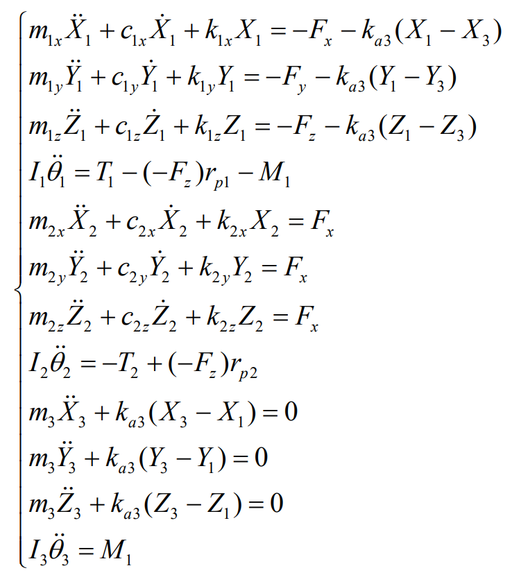
The nonlinear vibration differential equation of spiral bevel gear transmission system with additional damping ring is:


