
1. Spiral bevel gear model
Select a pair of spiral bevel gears, and the specific parameters are shown in the table.
| Pinion | Wheel | |
| Number of teeth | 11 | 43 |
| Pressure angle/° | 20 | 20 |
| Modulus | 6 | 6 |
| Helix angle/° | 35 | 35 |
| Axis intersection angle/° | 90 | 90 |
| Tooth width/mm | 50 | 50 |
| Rotation direction | Left-handed | Right-handed |
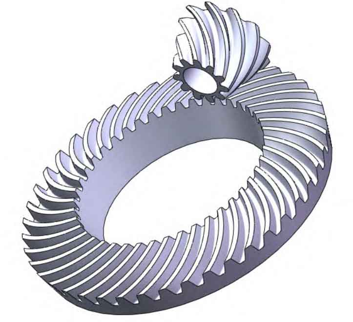
The tooth surface of spiral bevel gear is complex, and its machining principle and method are also more complex.
Use modern digital technology, use MATLAB software to program and calculate the discrete points on the tooth surface, import the discrete points into the 3D software SolidWorks, determine the line through the discrete points, form a surface from the line, determine the spiral bevel gear tooth slot, and then generate the spiral bevel gear by the array of tooth slots. Digital modeling can improve the accuracy of the tooth surface and reduce the processing error. The model is shown in Figure 1.
2. Establishment of finite element mesh model
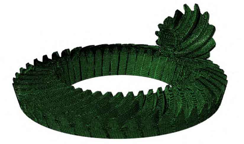
The tooth surface of spiral bevel gear is a complex surface with irregular shape. ABAQUS mesh generation is difficult to meet the requirements. Therefore, Hypermesh is selected as the mesh preprocessing software, and the finite element model is imported into ABAQUS software. The mesh function of Hypermesh software is very powerful. Use the Solid Map module to mesh the 3D model to obtain the required hexahedral mesh cells, as shown in Figure 2.
3. Boundary conditions and loading mode of dynamic contact analysis
In the finite element analysis of spiral bevel gears, the most important and easy to cause problems are the interaction module and the load loading module. The spiral bevel gears are in continuous contact and separation state during the meshing contact process, so the small slip contact type is used when setting the contact. When using Hypermesh pre-processing software for mesh division, the hexahedral mesh used is relative to other types of mesh.
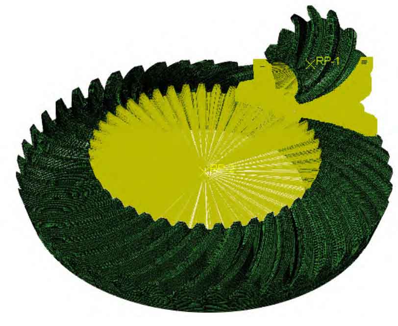
The finite element calculation can be carried out more accurately. For this model, the hexahedral mesh can only be translated and cannot be rotated, that is, the degree of freedom of rotation cannot be directly applied to the solid unit. Therefore, a reference point must be established at the centroid position of the central axis of the spiral bevel gear, and then a coupling constraint must be set. The constraint, rotation speed and torque of the big and small gears are added to the reference point. The small wheel is set as the driving wheel, and the rotational speed is set. The big wheel is the driven wheel, and the resistance torque is applied, This completes the setting of spiral bevel gear transmission conditions.