
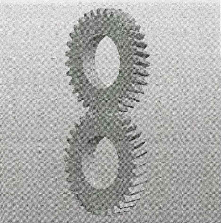
The geometric model of helical gear is established and assembled by using pro/e software. Here, it is agreed that the upper helical gear is gear 1 and the lower gear is driving gear. The geometric model is shown in Figure 1:
The finite element mesh model is shown in Figure 2. The contact between helical gears is set as friction contact, and the friction coefficient is 0.1. On the mesh division detail interface setting panel in ANSYS / workbench, set the relevancecenter to “fine”, and the others remain the default. The generated mesh is shown in Figure 2.
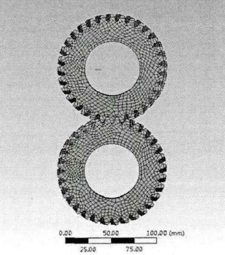
There are 50892 nodes and 9835 elements in the helical gear finite element mesh model. The helical gear finite element mesh is basically hexahedral element. It is obvious that its mesh quality is relatively high. The parameters to evaluate the quality of finite element mesh are aspectratio, jacbin, skewness, warpage angle. As shown in figures 3 to 5.


It can be seen that the meshing aspectratio is of high aspect ratio quality, with a minimum of 1.0498 and a maximum of 3.3736, and the parameter is usually required to be less than 5.
According to the general inspection, the standard wing angle is of high quality when it is less than 5 °, while the warpage in the workbench of the helical gear finite element model is evaluated by the factor, and the maximum is 0.022, so it can be seen that the warpage angle is very small. The meshing quality is high.
Through standard variance conversion, it can be seen that the Jacobian ratio is 0.61, while the helical gear finite element model requires that the Jacobian ratio is usually 0.6, and the mesh quality meets the requirements.