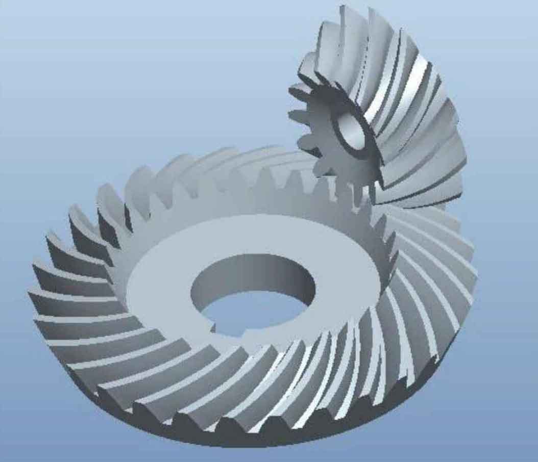
When the rigidity of differential case, support bearing and support housing of drive axle hypoid gear is relatively large, their elasticity can be ignored, and the rigidity of input shaft and half shaft is relatively small, so that the hypoid gear system is isolated from the input load and output load. The hypoid gear system is simplified into a pure torsional meshing vibration model, and a two degree of freedom meshing vibration model of hypoid gear is established separately. This simplification can analyze the inherent characteristics of the dynamic transmission error of gears without considering other factors. The dynamic meshing vibration model of drive axle hypoid gear mainly considers the influence of gear inertia on transmission error. In order to correspond to the static meshing model, the geometric and material properties of hypoid gear are the same as the static nonlinear analysis, and the element type is the same as the static finite element analysis. The differences are mainly described below.

1. Analysis type
There are linear and nonlinear dynamic analysis in ABAQUS. The dynamic analysis includes the influence of dynamic nonlinearity of inertia and load input, so nonlinear dynamic analysis is selected. Two analysis steps, contact and rotation, are defined. The contact analysis step is defined as the general / static analysis type, and the rotation analysis step is defined as the implicit dynamic analysis analysis type. The simulation duration of the analysis step is determined according to the rotation speed of the hypoid gear.
2. Contact properties
For dynamic models, the definition of interaction properties is more complex. The parameters in the interaction attribute module are the same as those in the static analysis. The surface contact property of the corresponding meshing tooth surface of each tooth is set to normal behavior, and the pressure interference is set to ‘hard’ contact. When the implicit dynamic analysis is run, serious convergence problems will occur initially, resulting in premature termination of the analysis step. Therefore, the rotation speed field of the hypoid gear can be defined in the predefined field as in the static analysis.
3. Boundary conditions
In the dynamic analysis process, the contact analysis step and the rotation analysis step are defined. In the contact analysis step, the torque is applied to the large hypoid wheel, while in the rotation analysis step, the rotation angle is applied to the small hypoid wheel. Since the teeth of the last two meshing hypoid gears in the contact analysis step have been meshed and contacted, there will be no sudden impact in the rotation analysis step to improve the convergence of the simulation. Other boundary conditions are the same as those in the static analysis.
