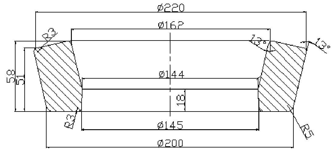
Basic dimensions: the shape of the blank is close to the shape of the driven spiral bevel gear after forming. The outer diameter D of the upper end of the blank is 220mm, the inner diameter is 162mm, the outer diameter of the lower end of the blank is 200mm, the inner diameter is 145mm, and the inclination is 13 °, as shown in Figure 1. The basic parameters of spiral bevel gear are shown in the table.
| Number of teeth | 39 | Cone distance (mm) | 115.27 |
| Modulus | 5.76 | Tooth crest height (mm) | 3.02 |
| Angular pressure | 22.5° | Full height of tooth (mm) | 11.37 |
| Graduation circle diameter (mm) | 224.64 | Midpoint helix angle | 29.43 |
| Tooth width (mm) | 34 | Rotation direction | Dextral |
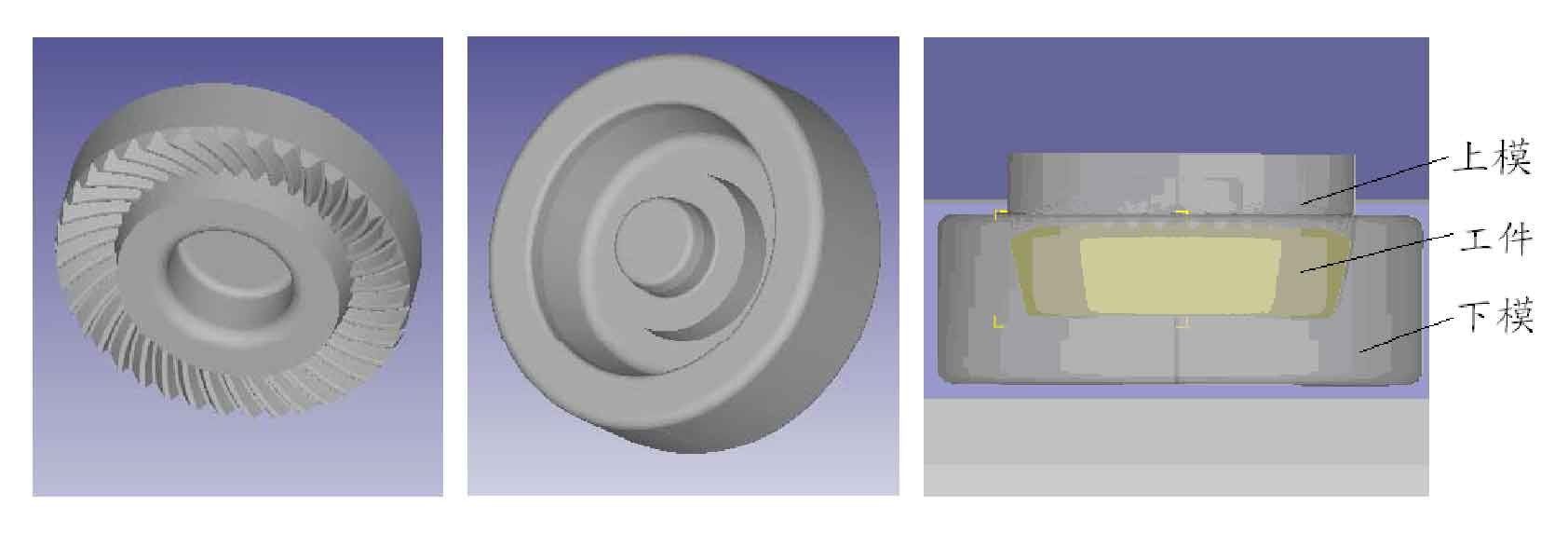
Use UG 3D modeling software to complete the geometric model design of die punch and die and forging. Figure 2 shows the three-dimensional geometric model diagram of driven spiral bevel gear punch and die and blank. After assembly and positioning in UG, export the data in turn and save it in STL format, then enter the pre-processing window, and then import it into DEFORM-3D finite element simulation software in STL file format. In the precision forging process of driven spiral bevel gear, the elastic deformation part of the material is far less than its plastic deformation part, so the elastic deformation of the deformation body can be ignored, that is, the workpiece is set as a rigid plastic body and the die is set as a rigid body. The hot forging temperature range of gear steel 20CrMnTi is 800 ~ 1200 ℃. The equipment is double disc friction press.
Due to the existence of spiral angle of spiral bevel gear and the effect of circumferential force during forming, the whole part of spiral bevel gear is selected as the simulation object. Create a new folder and import the assembly file in STL format into deform. Enter the pre-processing window and set the unit to SI system. Firstly, the grid is divided, the grid side length is measured, and the simulation step size is set according to the principle that the step size does not exceed 1 / 3 of the minimum side length. The forging is set to plastic and the punch and die are set to rigid. Then set the temperature of the forging and die, set the speed of the punch in the movement column, and then set the friction coefficient of the punch and die and the forging in turn. After setting the parameters of the pre-processing, check whether the set parameters are correct, and if they are correct, green will be displayed. If they are wrong, deform will be indicated in red. After the change, click the detection button again, generate the DB file after it is correct, and exit the pre-processing window, The numerical simulation operation can be started.


