1. Helical gear material selection
Helical gear materials can be roughly divided into four categories, such as Q235, Q275, 45 and other medium carbon steels for light load and low speed applications with low accuracy requirements; For example, 50Mn, 40Cr, 42SiMn and other alloy quenched and tempered steels shall be selected for occasions with medium load and medium speed and smooth transmission; For example, 20Cr, 20CrMnTi, 20CrMn5 and other low-carbon alloy carburized steels are selected for heavy load, high speed and large impact load; For example, 31CrMoV9, 35CrMo, 38CrMoAlA and other nitrided steels are used for precision transmission.
Obviously, the reduction gearbox of electric vehicle is under the harsh working condition of high speed (the maximum speed of driving wheel can reach 20000r/min), heavy load and large impact load, so it is very important to select the appropriate helical gear material. Here, 20CrMn5 low carbon alloy steel is selected.
2. Helical gear parameters and simulation process description
In order to better ensure the accuracy and reference significance of the simulation results, it is necessary to describe the parameters of the helical gear pair, as shown in the table.
| Driving wheel | Passive wheel | |
| Modulus (mm) | 2.25 | 2.25 |
| Tooth width (mm) | 28 | 30 |
| Number of teeth | 30 | 51 |
| Modification coefficient | 0.1136 | -0.1340 |
| Pressure angle (°) | 17.5 | 17.5 |
| Helix angle (°) | 32.5 | 32.5 |
| End face coincidence | 1.537 | 1.537 |
| Axial coincidence | 2.057 | 2.057 |
| Tooth side clearance (mm) | 0.05 | 0.05 |
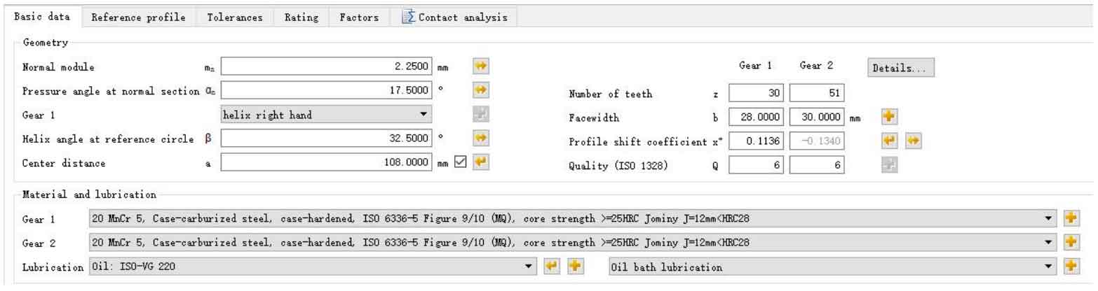
First, input the helical gear pair parameters shown in the table in the basic parameter module, set the gear 1 as the driving wheel, mesh along the right side of the helix, the center distance between the two gears is 108mm, the materials of gear 1 and gear 2 are 20MnCr5, the manufacturing accuracy is level 6, and the lubrication condition is oil bath lubrication, as shown in Figure 1.
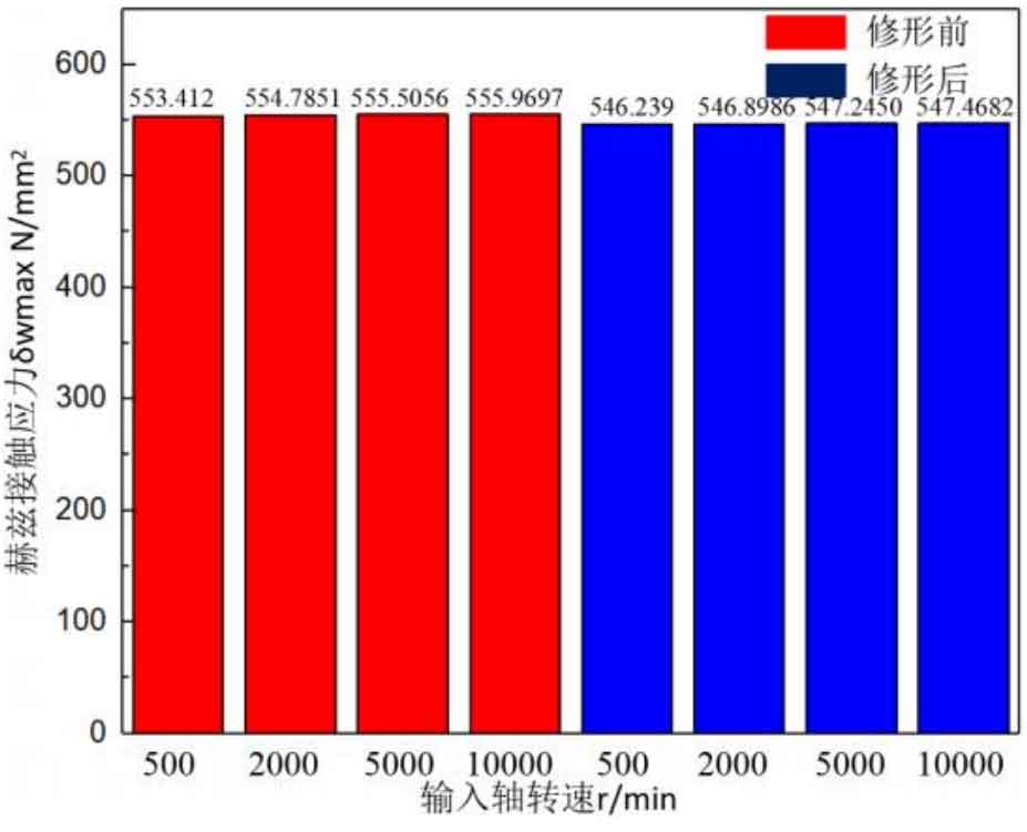
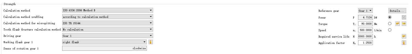
Then set the working condition. According to the previous research as shown in Figures 2 and 3, the speed has little influence on the transmission error and Hertz contact stress of the helical gear pair before and after modification. Therefore, the speed is set as 500r/min. In addition, the torque of vehicle helical gears is generally large, so the motor power and torque are set to 4.7124kw and 90N respectively in the Rating module m. The operation duration is set as 20000h. Considering that the automobile assembly is stable during operation, the service factor KA is set as 1.25. After setting, use ISO 6336:2006 Method B for simulation calculation, as shown in Figure 4.
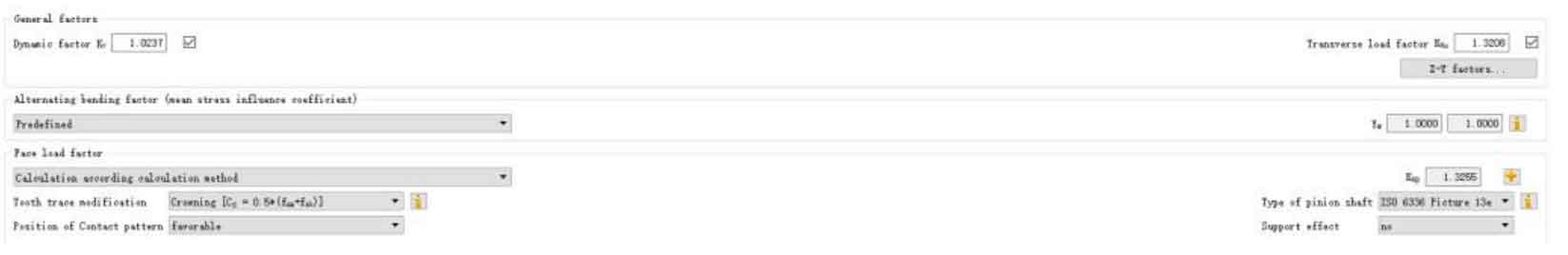
Then the dynamic coefficient Kv and transverse load coefficient KH α And tooth direction load coefficient KH β Set according to Figure 5.
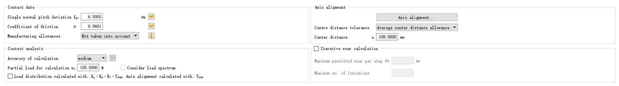
Finally, the contact analysis module is used to solve the calculation. The single normal pitch deviation fpt is set to 6 μ m. Coefficient of friction μ It is 0.0601 (calculated by software), and the shaft deformation offset error and processing and manufacturing error are not considered here. The detailed parameters are shown in Figure 6.