① Establishment of structural finite element model of helical gear system
The acoustic grid requires the grid size to be as uniform as possible. In order to ensure the consistency with the acoustic grid, the helical gear pair is simplified to an equivalent cylinder with the diameter of the graduation circle, so as to reduce the number of smaller elements. The geometric model of helical gear system is small, so tetrahedral elements are used for mesh generation, and the total number of elements is 56732.
② Establishment of acoustic boundary element model and field grid of helical gear system
The boundary element model of acoustic grid is a discrete two-dimensional surface grid. In order to avoid large errors caused by rough grid, it is usually assumed that there are six elements in the minimum wavelength, and the size of the largest element is less than one sixth of the shortest wavelength. For the secondary unit, the maximum unit size should be less than one-third of the shortest wavelength. For simple models, linear elements are usually used to meet the requirements.
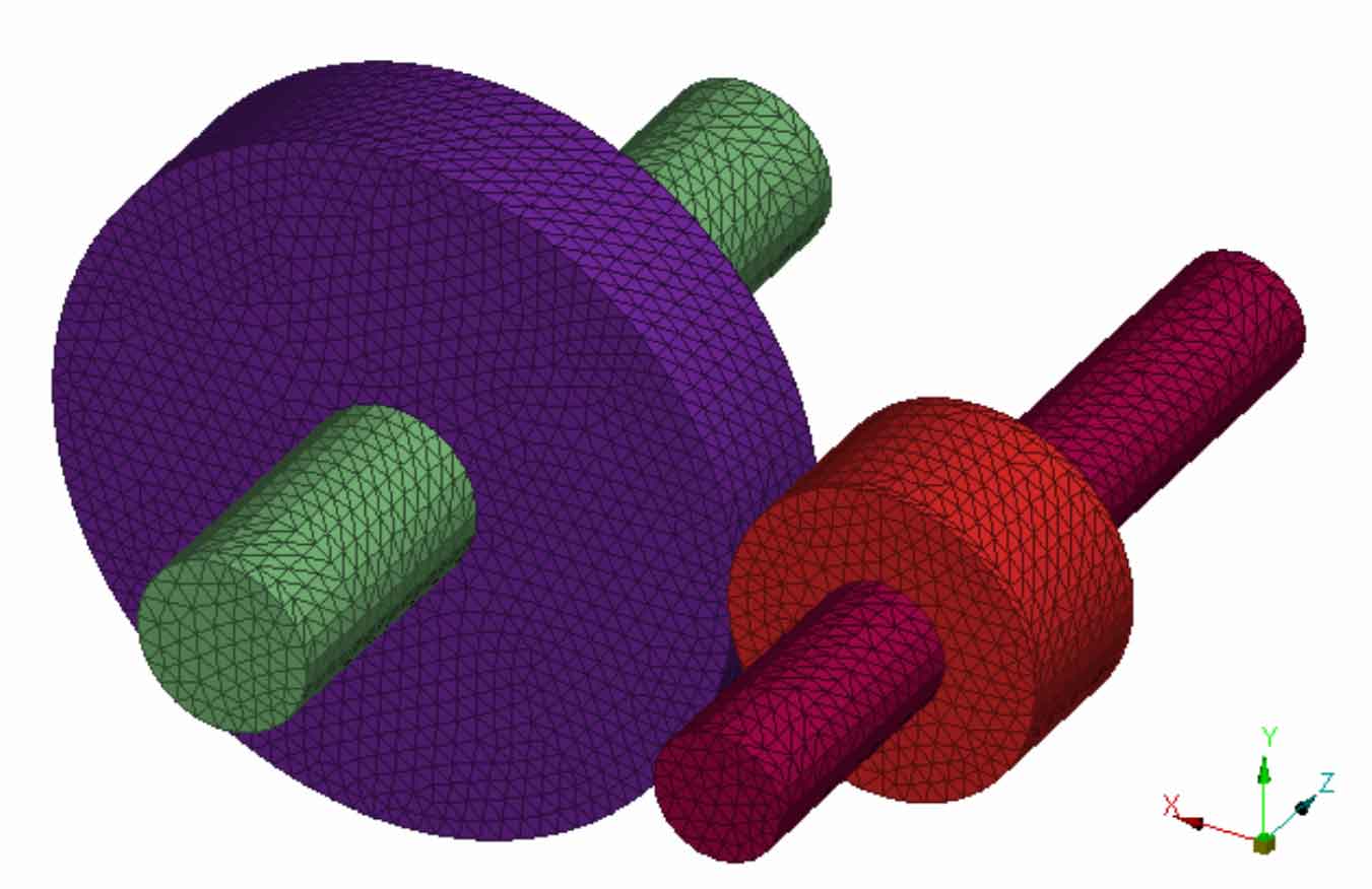
If the rotating speed of the helical gear system is 600r / min and the meshing frequency is 230hz, assuming that the maximum calculated frequency is five times of the meshing frequency, the meshing unit size should be less than 49mm (the fluid sound velocity is 340m / s). The size of the established helical gear system model is small, and the 5mm grid unit size is used for meshing, as shown in Figure 1.
Acoustic field point grid is to obtain sound pressure at different positions in space. Field point grid can define field point grids of different shapes according to the actual calculation model, such as spherical field point grid, hemispherical field point grid, cube or cuboid field point grid, cylindrical field point grid, etc. There are no strict requirements for the mesh generation of acoustic field points. The mesh size is selected according to the complex program of the actual model and the sound pressure value of the required position. For the helical gear system model, the rectangular field point grid is adopted in this paper. The grid size is 20mm and is arranged 20cm away from the helical gear surface, as shown in Figure 2.