The basic geometric structure of the ideal spiral bevel gear pair is formed by the rolling of two pitch cones, de1 and de2, whose cone tips coincide at the common intersection of the shafts. When the two pitch cones roll with each other, any meshing point on the tooth surface will move on the spherical surface, and the center point of the spherical surface coincides with the tip point of the two pitch cones, as shown in Figure 1 (a). The reference profile of the tooth profile is defined on the spiral cone pair at the tangent position between the two pitch cones, as shown in Figure 1 (b).
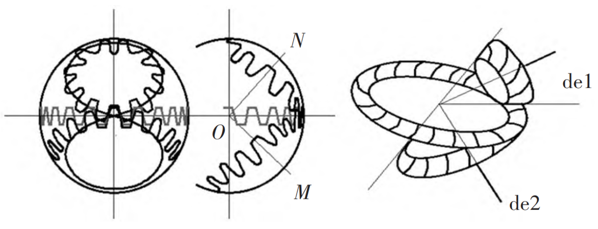
During the meshing of two spiral bevel gears, the meshing point between the two tooth surfaces moves on it. The motion path of the meshing point is called spherical involute, and at any meshing position of the meshing point, the tooth surfaces are perpendicular to each other, resulting in the continuous motion transmission from the driving gear to the driven gear. Here, based on the spherical involute tooth profile principle, starting from the geometric path of the involute, combined with the spiral bevel gear processing principle, The geometric profile of the tooth surface on the spherical surface can be determined. Then use Matlab language to solve the discrete points on the tooth surface and import them into the 3D modeling software UG, so as to establish the parametric geometric model of spiral bevel gear, as shown in the table.
| Parameter | Driven wheel | Driving wheel |
| Number of teeth z | 43 | 11 |
| Large end module m | 4.65 | 4.65 |
| pressure angle | 25° | 25° |
| Helix angle β | 33° | 33° |
| Axial intersection angle Σ | 90° | 90° |
| Addendum height factor f | 0.80 | 0.80 |
| Pitch diameter d (mm) | 199.97 | 51.16 |
| Pitch cone angle δ (°) | 75.6501 | 14.3797 |
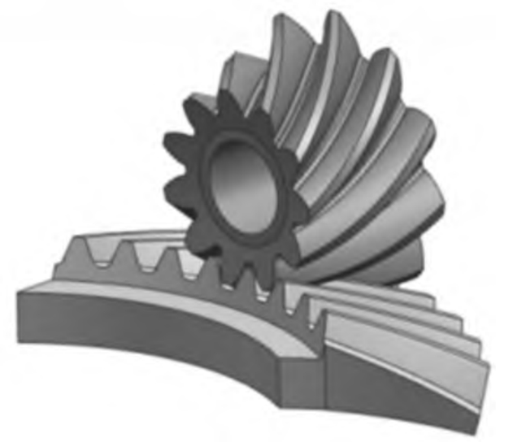
In order to simplify the subsequent finite element calculation, the big gear is cut. The final three-dimensional model of spiral bevel gear is shown in Figure 2.