
Because the backlash of gear pair is usually realized by controlling the tooth thickness deviation, there must be a certain tooth thickness deviation in the actual operation of the gear, and the manufacturing and installation errors and temperature changes will further affect the tooth thickness deviation. Firstly, the meshing stiffness and transmission error excitation calculation model of cylindrical gear pair considering tooth thickness deviation is established, and then the finite element model of cylindrical gear meshing pair considering tooth thickness deviation is established to pave the way for subsequent analysis.
Establishment of mesh stiffness and transfer error calculation model
The tooth thickness of cylindrical gear refers to the arc length between the tooth profiles on both sides of a tooth on any circumference, expressed as Si. For helical gear, it refers to the normal tooth thickness, and the tooth thickness of dividing circle is usually expressed as S. The tooth thickness deviation refers to the difference between the actual value and the nominal value of the tooth thickness on the gear indexing cylindrical surface Δ Es said. Δ ES is the upper deviation, Δ ESI is the lower deviation and t is the tooth thickness tolerance, as shown in Figure 1.

It can be seen that the tooth thickness deviation of involute cylindrical gear is a vector of size, direction (circumferential, normal and chordal) and position (fixed chord, dividing circle and middle circle). Therefore, in order to determine the size of tooth thickness deviation, its orientation should be clear, and its definition orientation and measurement orientation should be distinguished. If the measurement direction is wrong, then its measurement value will be distorted. The tooth thickness deviation is the normal tooth thickness deviation on the dividing circle.
In order to ensure the normal operation of the gear, there must be a proper backlash between each pair of meshing teeth. In order to meet the requirements of different backlash, there are mainly two methods: base center distance system and base tooth thickness system. Because it is convenient to thin the tooth thickness in gear cutting, most of the standards adopt the base center distance system. In the base center distance system, the tooth thickness is equivalent to the shaft of the base hole system, so the upper and lower deviation of the tooth thickness is negative. Gear designers usually give the code of tooth thickness limit deviation, and the corresponding tooth thickness deviation can be obtained by consulting the standard according to the code of tooth thickness limit deviation.
Kisssoft, a software for gear design and analysis, controls the actual tooth thickness deviation according to the range determined by the input tooth thickness deviation. Obviously, when the tooth thickness deviation is the same, the gear pair with any determined tooth thickness deviation can be obtained. In order to study the influence of different tooth thickness deviation on the vibration characteristics of gear pair, the meshing models of gear pair with tooth thickness deviation were established Δ Es0 means no tooth thickness deviation. Kisssoft is used to establish the calculation models of gear pair meshing stiffness excitation and transmission error excitation according to the above basic parameters and tooth thickness deviation, and the three-dimensional model of gear pair with different tooth thickness deviation is established, as shown in Figure 2.
Establishment of finite element model

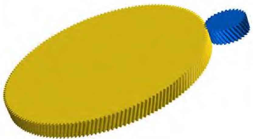
The three-dimensional model of gear pair with different tooth thickness deviation established in kisssoft is output in IGES format. The finite element modeling is carried out in the finite element pre-processing software ansa, and the finite element model of gear meshing pair with tooth thickness deviation is obtained, as shown in Figure 3. The finite element model has 380720 elements and 589128 nodes. When the boundary conditions are applied, the surface of the inner hole of the gear is regarded as a rigid body, and its five degrees of freedom are constrained, and only the degree of freedom about axial rotation is retained. The rotation speed of the pinion is 2010r / min, and the torque of the driven gear is 1812.5n · M. the face-to-face contact is used to define the contact of the gear pair, and the friction coefficient is 0.1. Finally, the model is imported into LS-DYNA in K file format for solution.