
The virtual model of spiral bevel gear NC machining machine tool is the image of its real entity in the virtual environment. The overall composition and size of the virtual model should be proportional to the composition structure of the real machine tool body. The overall virtual model is composed of a specific geometric model and an abstract motion model, which should meet the following two key requirements:
1) The geometric model of each part must truly reflect the structural composition of the machining machine tool, the geometric dimensions of the main parts of the machine tool, the relative positions between the parts of the machine tool, and the spatial topological relationship between the parts of the machine tool;
2) The motion model of the NC machine tool should truly reflect its own natural structure and motion law and its motion characteristics in the tooth surface forming process, the motion range of each main component, as well as the relative motion relationship between components, and be able to accurately execute the motion results of each component, so that the machining machine tool model should be consistent with the operation of the real machining machine tool when realizing relevant operations.
On the premise of meeting the above requirements, considering that in the process of tooth surface forming motion simulation, the model of spiral bevel gear processing machine tool only needs to show the shape and motion characteristics of its main visible parts, so the geometric model and motion model of the machine tool can be simplified, and the machine tool components that are irrelevant to or do not need to be displayed in the process of tooth surface forming motion simulation, such as ball screws, coolant pipelines, hydraulic pumps Connecting bolts, etc. may not be considered. Therefore, the modeling method of spiral bevel gear processing machine tool is also divided into two parts: Geometric Modeling and kinematic modeling. The specific methods are as follows:
1) Establishment of geometric model of spiral bevel gear machining machine tool
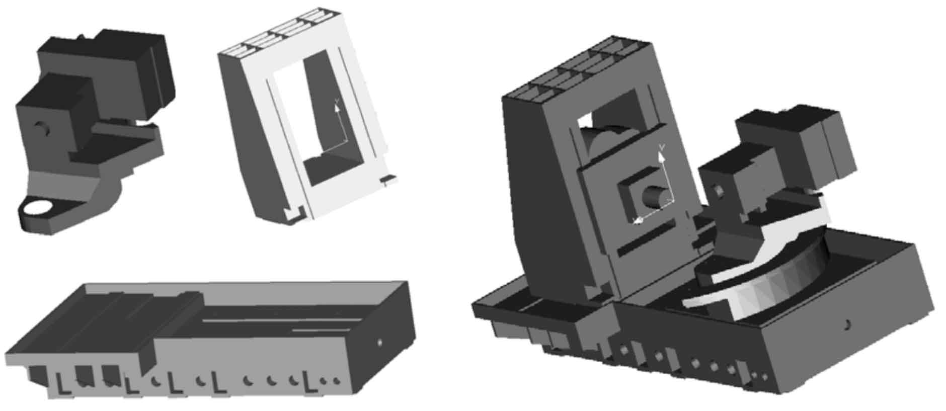
A spiral bevel gear machining machine tool based on hierarchical assembly model is established. The geometric model of spiral bevel gear processing machine tool is divided into four levels: the overall assembly level of the machine tool, the assembly level of main components, the main parts level and the geometric basic form level according to the idea of from top to bottom and from the whole to the part. The overall model of the machine tool is finally composed of the geometric basic form. The overall assembly layer of the machine tool that describes the aggregation relationship between the whole machine tool and the main parts is the top layer of the whole hierarchical model. The main part assembly layer that describes the aggregation relationship between the main parts and the main parts is below the overall assembly layer of the machine tool. The main part layer that describes the aggregation relationship between the main parts and the geometric basic body is below the component assembly layer, and the structural layer of the geometric basic body is at the bottom. There is a “subordinate relationship” between the division units at different levels, while there is a “relative position constraint” relationship between the division units at the same level. Therefore, before constructing the geometric model of spiral bevel gear processing machine tool, its composition and assembly relationship should be analyzed according to the above four levels of relationship diagram, and when constructing the geometric model of machine tool, the assembly should be carried out according to the relative position relationship between various parts. The figure is the effect drawing of the geometric model of spiral bevel gear processing machine tool.
2) Establishment of motion model of spiral bevel gear NC machining machine tool
The movement of the real spiral bevel gear NC machining machine tool in the working process reflects the following three characteristics:
① The motion of each part of the spiral bevel gear NC machining machine tool has a fixed range of motion in the tooth surface forming process. The definition of the motion coordinate system of each part of the machine tool is consistent with the right-hand Cartesian coordinate system.
② The main moving parts of each machine tool can only realize the translational movement along a certain straight line or the rotary movement around a certain axis at the same time. The forming of complex tooth surface is realized by multi axis linkage control of several main moving parts acting at the same time.
③ The moving axes of spiral bevel gear machining machine tools have the characteristics similar to those of general multi axis machining centers, that is, they have hierarchical relative motion relations.
According to the above points, the following definitions are made according to the motion characteristics of spiral bevel gear NC machining machine tool in the working process:
① Determine each component model in the geometric model of the machine tool that can move relative to other components, and define it as a motion node;
② According to the assembly relationship between the main moving parts of the machine tool, the hierarchical relationship between the moving nodes is defined to form a motion relationship tree;
③ Determine the motion mode of each motion node, define the motion variables at the motion node, and form the motion variable table of the overall machine tool model;
④ By clearly defining the relationship between the motion variables and the motion axis, the motion axis table of the machine tool model is formed.