
In the manufacturing of automotive components, particularly bevel gears used in drive axles, carburizing and quenching heat treatment processes are critical for enhancing surface hardness, wear resistance, and overall durability. However, these processes often introduce distortions and residual stresses due to phase transformations and thermal gradients. Material composition fluctuations can significantly influence the outcomes of such heat treatments, yet systematic analyses of these effects on bevel gears are limited. This study investigates the impact of material composition variations on the carburizing and quenching performance of 22CrMo bevel gears using finite element methods. By establishing material property databases based on the upper and lower limits of elemental composition ranges, we simulate the heat treatment process and evaluate key parameters such as surface carbon concentration, microstructural evolution, and deformation. The findings provide insights into how compositional changes affect the quality and performance of bevel gears, aiding in optimizing manufacturing processes for improved consistency and reliability.
The 22CrMo steel, commonly used for high-strength bevel gears, exhibits a range of elemental compositions as specified in industrial standards. To assess the influence of composition fluctuations, we defined two material datasets: one representing the upper limit (ωmax) and the other the lower limit (ωmin) of the elemental range. The chemical compositions for these datasets are summarized in Table 1. Using material database software, we generated comprehensive property databases for both ωmax and ωmin, incorporating data on diffusion coefficients, thermal conductivity, specific heat, and other thermophysical properties essential for simulating carburizing and quenching. These databases enable accurate modeling of the heat treatment process, accounting for variations in淬透性 and other material responses.
| Element | ωmin | ωmax |
|---|---|---|
| C | 0.19 | 0.25 |
| Si | 0.17 | 0.37 |
| Mn | 0.55 | 0.90 |
| Cr | 0.85 | 1.25 |
| Mo | 0.35 | 0.45 |
| P | 0.03 | 0.03 |
| S | 0.010 | 0.03 |
| Al | 0.020 | 0.045 |
The mathematical models employed in this simulation encompass several key aspects: the carburizing field model for carbon diffusion, the heat conduction model for temperature evolution, the phase transformation model for microstructural changes, and the stress-strain model for deformation analysis. The carburizing process is governed by Fick’s second law, which describes the diffusion of carbon atoms in the steel matrix. The equation is expressed as:
$$ \frac{\partial C}{\partial t} = \frac{\partial}{\partial x_i} \left( D \frac{\partial C}{\partial x_i} \right) $$
where \( C \) is the carbon concentration, \( t \) is time, \( x_i \) is the spatial coordinate, and \( D \) is the diffusion coefficient of carbon in the iron-based alloy. The diffusion coefficient depends on temperature and carbon content, as given by:
$$ D(T,C) = D_{0.4} \exp\left(-\frac{Q}{RT}\right) \exp\left(-B(0.4 – C)\right) $$
Here, \( D_{0.4} = 25.5 \, \text{mm}^2/\text{s} \) is the diffusion constant, \( B \) is a constant relating diffusion to carbon concentration, \( Q = 141 \, \text{kJ/mol} \) is the activation energy for carbon diffusion, and \( R = 0.8 \, \text{J/(mol·K)} \) is the gas constant. For the ωmax material, the diffusion coefficients at various temperatures are provided in Table 2, illustrating how composition affects carbon mobility during carburizing.
| Carbon Mass Fraction (%) | 750°C | 800°C | 850°C | 900°C | 930°C |
|---|---|---|---|---|---|
| 0.2 | 4.38×10⁻⁷ | 1.008×10⁻⁶ | 2.155×10⁻⁶ | 4.32×10⁻⁶ | 6.37×10⁻⁶ |
| 0.4 | 6.22×10⁻⁷ | 1.409×10⁻⁶ | 2.968×10⁻⁶ | 5.87×10⁻⁶ | 8.59×10⁻⁶ |
| 0.6 | 8.81×10⁻⁷ | 1.963×10⁻⁶ | 4.075×10⁻⁶ | 7.95×10⁻⁶ | 1.155×10⁻⁵ |
| 0.8 | 1.242×10⁻⁶ | 2.726×10⁻⁶ | 5.577×10⁻⁶ | 1.073×10⁻⁵ | 1.549×10⁻⁵ |
| 1.0 | 1.746×10⁻⁶ | 3.772×10⁻⁶ | 7.608×10⁻⁶ | 1.446×10⁻⁵ | 2.071×10⁻⁵ |
The heat conduction model accounts for temperature changes and phase transformation latent heat. The governing equation is:
$$ \rho c \dot{T} – \frac{\partial}{\partial x_i} \left( k \frac{\partial T}{\partial x_i} \right) + \sum \rho_I l_I \dot{\xi}_I = 0 $$
where \( \rho \) is density, \( c \) is specific heat capacity, \( k \) is thermal conductivity, \( l_I \) is latent heat of phase transformation, and \( \dot{\xi}_I \) is the rate of volume fraction change for phase I. For the ωmax material, the specific heat capacity and thermal conductivity as functions of temperature are depicted in Figure 1a and 1b, respectively. The latent heats for transformations such as austenite to ferrite, pearlite, bainite, and martensite are derived from literature, with values around \( 5.9 \times 10^8 \) to \( 6.4 \times 10^8 \, \text{J/m}^3 \). The boundary condition for heat transfer is given by:
$$ -k \frac{\partial T}{\partial x_i} n_i = h (T_S – T_\infty) $$
where \( h \) is the heat transfer coefficient, \( n_i \) is the unit normal vector, \( T_S \) is the surface temperature, and \( T_\infty \) is the ambient temperature. During quenching, the convection heat transfer coefficient for oil cooling is applied, as shown in Figure 2 for ωmax.
The phase transformation model includes diffusion-based transformations for ferrite, pearlite, and bainite, and a non-diffusive transformation for martensite. The austenitization during heating is modeled as:
$$ \xi_A = 1 – \exp \left[ A_0 \left( \frac{T_0 – T_{AC1}}{T_{AC3} – T_{AC1}} \right)^{D_0} \right] $$
where \( \xi_A \) is the austenite volume fraction, \( T_0 \) is the material temperature, \( A_0 = -4 \), \( D_0 = 2 \), and \( T_{AC1} \) and \( T_{AC3} \) are the start and end temperatures of austenite transformation. For cooling, diffusion transformations follow the Johnson-Mehl-Avrami equation:
$$ \xi_I = 1 – \exp(-k t^n) $$
and martensite transformation uses the Koistinen-Marburger equation:
$$ \xi_M = 1 – \exp[-\alpha (T_S – T_0)] $$
where \( \xi_M \) is martensite volume fraction, \( T_S \) is martensite start temperature, and \( \alpha = 0.011 \).
The stress-strain model incorporates various strain components to predict deformation and residual stresses. The total strain rate is expressed as:
$$ \dot{\varepsilon}_{ij} = \dot{\varepsilon}_{ij}^t + \dot{\varepsilon}_{ij}^e + \dot{\varepsilon}_{ij}^p + \dot{\varepsilon}_{ij}^{tr} + \dot{\varepsilon}_{ij}^{tp} $$
where the terms represent thermal, elastic, plastic, transformation, and transformation plasticity strain rates, respectively. The plastic flow stress is a function of strain, strain rate, and temperature: \( \bar{\sigma} = \bar{\sigma}(\varepsilon, \dot{\varepsilon}, T) \). Key thermophysical properties for ωmax, such as thermal expansion coefficient, elastic modulus, Poisson’s ratio, and transformation expansion coefficient, are illustrated in Figure 3a-d, highlighting how material composition influences these parameters.
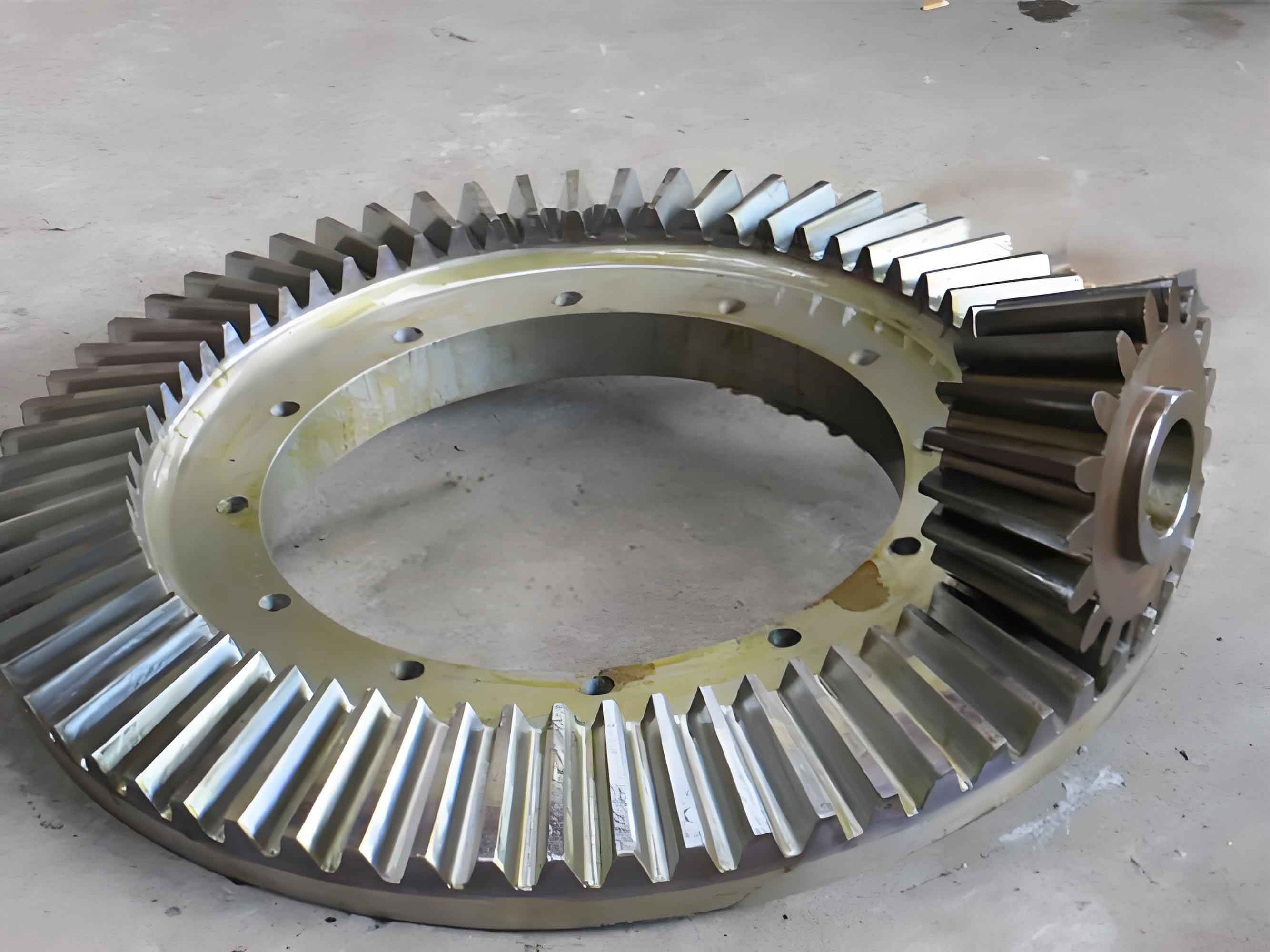
For the geometric model, we focused on a segment of a passive bevel gear from a truck drive axle to reduce computational complexity while maintaining accuracy. The full and partial models are shown in Figure 4, with the partial model capturing critical regions like tooth surfaces and the gear base. The heat treatment process follows a standard carburizing and quenching cycle: heating to 930°C for carburizing, followed by cooling to 850°C for diffusion, and then quenching in oil. The detailed thermal profile is depicted in Figure 5, ensuring realistic simulation of industrial practices for bevel gears.
In the results analysis, we first examined the carbon concentration distribution after carburizing. For both ωmax and ωmin bevel gears, the surface carbon mass fraction reached approximately 0.9% after the strong carburizing stage and decreased to about 0.85% after diffusion. The carbon profiles from the surface to the core, as shown in Figure 6a for ωmax and Figure 6b for ωmin, exhibited smooth transitions with minimal differences between the two compositions. This indicates that material composition fluctuations have a negligible impact on the carburizing layer characteristics in 22CrMo bevel gears, as the diffusion processes are dominated by temperature and time rather than elemental variations.
Next, we analyzed the microstructural evolution after quenching. The martensite volume fraction distributions for ωmax and ωmin are presented in Figure 7a and 7b, respectively. For ωmax, the tooth surface comprised over 90% martensite, while the core contained about 35% martensite along with significant bainite. In contrast, ωmin showed a similar martensite-rich surface but virtually no martensite in the core, which was predominantly bainite. This disparity arises from the higher淬透性 of ωmax due to its elevated alloy content, facilitating martensite formation even in slower-cooling regions. The bainite volume fractions, illustrated in Figure 8a for ωmax and Figure 8b for ωmin, further confirm this: ωmax had约 65.4% bainite in the core, whereas ωmin exhibited nearly complete bainite transformation. These findings underscore how composition fluctuations alter phase distributions in bevel gears, potentially affecting mechanical properties like hardness and toughness.
Deformation analysis focused on tooth surface distortion and base warping, critical for the assembly and performance of bevel gears. The results for ωmax and ωmin are summarized in Table 3, with deformation patterns shown in Figure 9a-d for ωmax and Figure 10a-d for ωmin. ωmax bevel gears experienced greater deformation, with concave surface distortions up to 59.9 μm and convex surface distortions of 42.3 μm, compared to 44.7 μm and 37 μm for ωmin, respectively. Base warping also differed: ωmax had inner warping of 132 μm and outer warping of 66.8 μm, while ωmin showed 46.6 μm and 89.4 μm. The overall deformation magnitude was higher for ωmax (65.2 μm) than for ωmin (42.8 μm), attributed to the more extensive martensitic transformation and associated volumetric expansion in high-淬透性 material. This highlights the importance of controlling composition to minimize distortions in bevel gears during heat treatment.
| Material | Concave Surface Deformation | Convex Surface Deformation | Inner Base Warping | Outer Base Warping | Overall Deformation |
|---|---|---|---|---|---|
| ωmax | 59.9 | 42.3 | 132 | 66.8 | 65.2 |
| ωmin | 44.7 | 37 | 46.6 | 89.4 | 42.8 |
To validate the simulation model, we compared results with experimental data from a production 22CrMo bevel gear with a composition close to ωmax. The measured chemical composition included C: 0.246%, Si: 0.307%, Mn: 0.865%, Cr: 1.14%, and Mo: 0.398%. Microstructural examination revealed a martensitic surface and a bainite-rich core, consistent with the simulation predictions for ωmax. Deformation measurements from gear inspection, as detailed in Table 4 for concave surfaces and Table 5 for convex surfaces, showed a concave distortion of 63.2 μm and convex distortion of 39.3 μm, aligning closely with the simulated values of 59.9 μm and 42.3 μm (error rates of 5% and 7%, respectively). This agreement confirms the reliability of the finite element model for predicting heat treatment outcomes in bevel gears.
| Position 1 | Position 2 | Position 3 | Position 4 | Position 5 | Position 6 | Position 7 | Position 8 | Position 9 | Position 10 | Position 11 |
|---|---|---|---|---|---|---|---|---|---|---|
| 22 | 24.2 | 24.4 | 24.1 | 22 | 21.5 | 19.4 | 18.1 | 15.7 | 13.9 | 12.7 |
| 31.4 | 36.5 | 33.0 | 31.5 | 27.4 | 26.6 | 23.9 | 24.2 | 21.1 | 16.7 | 15.8 |
| 30.1 | 33.9 | 33.5 | 33.1 | 28.7 | 28.5 | 24.7 | 23.3 | 20.2 | 15.9 | 13.9 |
| 23.6 | 27.0 | 27.1 | 26.5 | 24.1 | 22.0 | 19.8 | 20.0 | 16.3 | 14.3 | 11.4 |
| 5.5 | 11.3 | 15.1 | 15.2 | 14.9 | 13.7 | 10.6 | 11.3 | 9.4 | 7.8 | 6.7 |
| -9.1 | -3.4 | 1.6 | 2.3 | -0.5 | 0 | -0.5 | 0.7 | -0.9 | -1.8 | -1.4 |
| -27.1 | -20.5 | -16.2 | -14.9 | -14.3 | -13.8 | -15.7 | -14.1 | -14.0 | -13.5 | -11.9 |
| -46.6 | -41.0 | -33.7 | -29.8 | -28.5 | -28.5 | -29.2 | -25.2 | -23.8 | -22.1 | -20.9 |
| -58.4 | -49.6 | -43.5 | -39.6 | -36.6 | -34.7 | -33.1 | -30.0 | -27.9 | -25.7 | -24.5 |
| -42.5 | -38.9 | -33.7 | -37.8 | -35.6 | -34.5 | -33.6 | -34.1 | -31.5 | -32.1 | -29.9 |
| -34.1 | -36.2 | -33.5 | -34.3 | -32.1 | -33.6 | -31.9 | -29.0 | -31.3 | -24.2 | -29.5 |
| Position 1 | Position 2 | Position 3 | Position 4 | Position 5 | Position 6 | Position 7 | Position 8 | Position 9 | Position 10 | Position 11 |
|---|---|---|---|---|---|---|---|---|---|---|
| 11.9 | 5.0 | 4.3 | 2.1 | 3.5 | -1.5 | -4.9 | -5.4 | -11.2 | -19.0 | -25.6 |
| 13.0 | 9.3 | 6.4 | 3.0 | 0.9 | -3.8 | -10.1 | -16.6 | -21.1 | -27.3 | -31.9 |
| 8.1 | 4.5 | 0.5 | -4.4 | -9.3 | -11.3 | -15.5 | -20.0 | -27.0 | -29.6 | -37.9 |
| -1.0 | -3.9 | -9.8 | -11.6 | -14.1 | -12.3 | -15.0 | -21.1 | -26.1 | -26.7 | -32.7 |
| -3.0 | -8.4 | -10.2 | -10.4 | -10.8 | -11.3 | -10.3 | -15.3 | -18.1 | -20.1 | -24.0 |
| 0.1 | -4.0 | -2.8 | -4.7 | -0.7 | 0 | -0.2 | -1.6 | -4.1 | -6.3 | -10.3 |
| 9.5 | 8.1 | 7.4 | 8.9 | 10.8 | 12.1 | 16.5 | 14.3 | 12.3 | 12.3 | 11.2 |
| 14.9 | 15.4 | 16.1 | 16.0 | 20.4 | 23.4 | 24.6 | 25.0 | 24.4 | 25.9 | 21.1 |
| 17.2 | 17.9 | 19.1 | 18.7 | 20.9 | 27.0 | 27.6 | 32.5 | 27.9 | 30.9 | 27.4 |
| 17.1 | 16.9 | 19.0 | 18.5 | 20.1 | 23.9 | 26.1 | 28.9 | 30.6 | 31.5 | 34.4 |
| 17.7 | 22.2 | 17.8 | 19.8 | 19.8 | 21.1 | 22.4 | 21.5 | 25.7 | 22.3 | 21.6 |
In discussion, the simulations reveal that material composition fluctuations in 22CrMo bevel gears primarily affect phase transformations and deformation, with minimal impact on carburizing depth. The higher淬透性 of ωmax promotes martensite formation in the core, leading to greater volumetric expansion and distortion compared to ωmin. This aligns with theoretical expectations, as alloy elements like Cr and Mo enhance hardenability by delaying diffusion transformations. Consequently, controlling composition within narrow limits can reduce variability in bevel gear quality. Additionally, the models demonstrate that pre-simulation using material databases can predict heat treatment outcomes, enabling proactive adjustments in industrial settings.
In conclusion, this study underscores the significant influence of material composition fluctuations on the carburizing and quenching performance of 22CrMo bevel gears. While carbon distribution remains largely unaffected, phase organization and deformation are highly sensitive to compositional changes. The ωmax composition results in more martensite and greater distortion, whereas ωmin leads to bainite dominance and reduced deformation. Validation with experimental data confirms the accuracy of the finite element approach. For manufacturers of bevel gears, maintaining consistent material composition is crucial to minimizing distortions and ensuring reliable performance. Future work could explore optimizing heat treatment parameters to compensate for compositional variations, further enhancing the durability of bevel gears in automotive applications.