

Taking MATLAB as a tool, the three-dimensional virtual gear hobbing of high-order elliptical spur gear and helical gear is carried out based on the formula. The processing results of Spur Gear Hobbing with the parameters shown in Figure 1 are shown in Figure 2, and the processing results of helical gear hobbing are shown in Figure 3. Virtual gear hobbing shows the tool path under the control of gear hobbing model, can pre display the actual tooth profile shape, can verify the theory in an economical and effective way, and avoid blind machining. The spur and helical gears shown in Fig. 2D and Fig. 3D are overcut because some pitch curves are concave and the concave part of the tool processing interferes with the external convex tooth shape; All other gears shown in Fig. 2 and Fig. 3 have convex pitch curves, and the hobbing results of virtual gear hobbing are correct and can be rolled.


Based on the formula, the high-order elliptical gear machining module is developed on the arm + DSP + FPGA hobbing NC platform, and the typical high-order elliptical gears with three parameters are hobbed. The results are shown in Fig. 4. FIG. 4A is a pitch curve externally convex 4th order spur gear (a = 150, n = 4, e = 0.05, Mn = 8), and Fig. 4b is a pitch curve externally convex 4th order helical gear (a = 150, n = 4, e = 0.05, Mn = 8, β C = 14.49 °), the real object obtained by gear hobbing is consistent with the pitch curve and tooth profile of Fig. 2C and Fig. 3C (with the same parameters) obtained by virtual machining, which proves that the linkage model is correct and feasible and the virtual machining result is accurate. Fig. 4C is a 3D theoretical gear model established according to the parameters of Fig. 2D (a = 150, n = 4, e = 0.15, Mn = 8). Part of the pitch curve is concave, and the gear hobbing and hobbing real object is shown in Fig. 4D. Compared with FIG. 4C, over cutting leads to serious deformation of the tooth profile, which does not meet the gear meshing principle; Figure 4D is consistent with figure 2D.
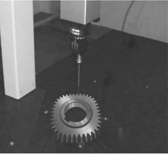

Taking the outer convex 4th order elliptic spur gear as an example, the nodes, vertices and tooth root points on the gear tooth profile are selected, and the coordinates of two tooth profile points between the three points are taken for detection on the CMM, and 390 measured coordinate points are detected (the selection of 78 nodes on 39 teeth of the gear is obtained by slightly marking the intersection point between the pitch curve of the gear end face and the actual tooth profile with a micro milling cutter on the NC machine tool). The three coordinate measuring machine is used to detect the intersection point between the marked pitch curve and each tooth profile, the vertex on the tooth profile, the tooth root point, and the two points taken between the three points (as shown in Fig. 5 and Fig. 6), compare the 390 measured coordinate positions on the non-circular gear tooth profile with the theoretical tooth profile coordinate positions by the CMM. Through the measured data of 78 nodes of the tooth profile, the deviation of each node coordinate in the X and Y coordinate directions can be listed δ X and δ Y frequency distribution in a certain interval, and then take the corresponding frequency as the ordinate and the middle value of the measured node as the abscissa to make the measured deviation distribution diagram of each tooth profile node of non-circular gear, as shown in Fig. 7. It can be seen from Fig. 6 and Fig. 7 that the interval frequency of the measured deviation between the tooth profile node coordinates detected by the actual gear hobbing machining gear and the theoretical tooth profile node coordinates is roughly the same Similarly, the actual tooth profile is consistent with the theoretical tooth profile. Through analysis in combination with Fig. 4, it is proved that the hobbing conditions of the actual machined pitch curve and the results of the virtual machined pitch curve are correct. In Fig. 6, it is also found that the coordinate deviation value of the tooth profile node near the minimum curvature radius of the pitch curve of the non-circular gear is large, which provides a basis for further research on the hobbing error of high-order non-circular gear It lays a foundation for the study of mechanism.
