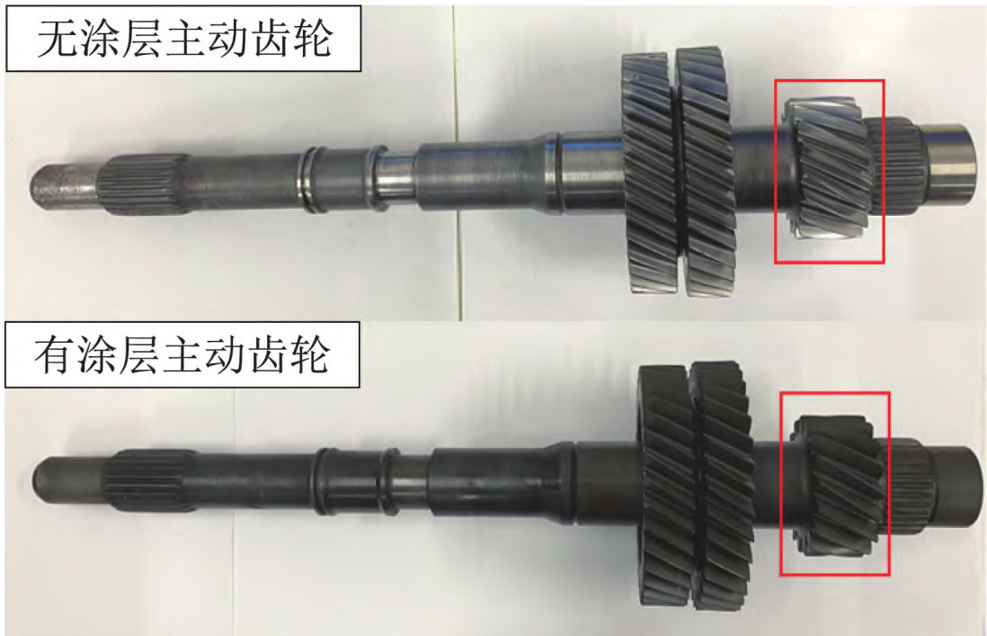
The first gear helical gear pair system of an automatic transmission has the characteristics of high load and high fatigue limit demand. In order to explore ways to improve the contact fatigue life of helical gears, a manganese phosphate conversion coating was applied to the surface of the first gear helical gear, and relevant experimental studies were conducted. The physical image of the helical gear with/without coating is shown in Figure 1.
1. Accuracy detection of helical gears
Using the FCL Å 250H helical gear precision testing bench, perform precision testing on the pre produced/uncoated helical gears after running in. Measure parameters such as tooth profile error, tooth orientation error, and cumulative deviation of tooth pitch using two tooth surfaces as a group.
At the same time, in order to study the effect of manganese phosphate conversion coating on the meshing performance of helical gears after running in, the Tokyo Precision SURFCOM NEX 001SD-12 surface roughness measuring instrument was used to detect the surface roughness of helical gears with/without coating. According to the actual tooth width of the experimental helical gear pair, the measuring length of 1.5 mm and the measuring speed of 0.06 mm/s are selected to obtain the arithmetic mean deviation Ra and the maximum height Rz of the tooth surface profile.
2. Contact Fatigue Life Test for Helical Gears
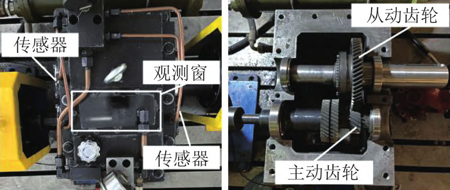
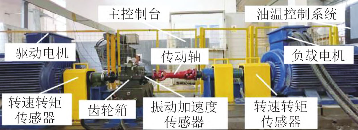
The contact fatigue life test and comprehensive evaluation of transmission performance of carburized heat treated 20MnCrS5 transmission helical gears were conducted through a two motor helical gear contact fatigue pitting experimental platform. The experimental platform for contact fatigue pitting corrosion of helical gears is shown in Figure 2, which mainly consists of a driving motor, a load motor, a speed torque sensor, a transmission shaft, a gearbox, an oil temperature control system, and a main console. Among them, the helical gearbox is shown in Figure 3. Vibration acceleration sensors are installed on the rear cover of the input shaft and the front cover of the output shaft of the helical gearbox, respectively, for real-time monitoring and collecting vibration acceleration signals during the meshing process of the helical gear.
In the initial running in stage, set the input speed to 1500 r/min, input torque to 150 N · m, and continue running for 2 hours; Gradually increase the speed and torque until the input speed is 2500 r/min and the input torque is 230 N · m. Conduct contact fatigue pitting experiments on the helical gear, and regularly check the condition of the tooth surface through a transparent observation window on the helical gear box.