1) Define the ultimate load and maximum fatigue load
The sample is fixed on the fixture by two round pins. In order to apply the load to the loading hole through the round pin, the size of the round pin and the loading hole needs to realize the fit of the pin hole. The load on the sample is evenly distributed, as shown in Figure 1.
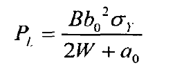
The prefabrication of fatigue cracks is carried out according to the ductile fracture toughness JIC test method of metal materials. Based on the above wire cutting method, the pre crack method is based on machining a small crack with a length of 4mm and a width of 0.12mm. Load alternating cyclic load on MTS810 electro-hydraulic servo material experimental system. Firstly, calculate the limit load of standard compact tensile specimen:
The fatigue load at the time of fatigue induced crack shall meet the following conditions: pfmax ≤ 0.4 α 0 and pfmin ≥ 0.1 α 0 Load amplitude pfmax pfmin ≥ 0.9pfmax. Therefore, the maximum fatigue load pfmax shall not be greater than 0.4pl, and the minimum fatigue load pfmin ≤ 0.1pfmax.
In this study, the yield load is calculated according to the fracture strength theory. In the test, the maximum fatigue load shall be less than the load when yielding occurs. The maximum load and minimum load shall meet the following requirements:
2) Prefabricated fatigue crack
Before the formal fatigue crack growth test, the samples need to be pre cracked. In the process of prefabricating cracks, the maximum stress value will gradually decrease with the continuous loading, but each reduction value shall not exceed 20% of the previous value. The loading mode adopts unidirectional axial load. During this period, pay attention to whether the sample has cracks and pay attention to the change of test frequency. If a crack is observed or the frequency changes rapidly within a certain number of cycles, it indicates that a crack has occurred. Follow the above requirements until the pre crack length reaches 1mm and the pre crack stage ends.
3) Experimental conditions
The formal loading is carried out at room temperature and atmospheric conditions, and the loading mode n is unidirectional axial loading. Since the national standard only gives the maximum allowable load of standard compact tensile test, in order to study the sample expansion rate under different stress ratio relations, two groups of different stress ratios r = 0.1 and 0.6 are designed to test three samples under the same amplitude load and different stress ratio. All specimens tested have the same loading conditions except for different stress ratios during fatigue propagation. The control modes of fatigue crack growth rate test are constant load and sine wave load. When the stress ratio r = 0.1, the load range is 0.55-5.5kn; When the stress ratio r = 0.6, the load range is 2.1-3.5kn and the test frequency is 10Hz. Mts632.02f-20 displacement extensometer with computer control and data acquisition is used to collect experimental data such as crack length. Until the fatigue failure of the test sample, the test is completed and the test sample is taken out. The crack length finally measured by extensometer starts from the midpoint of the line connecting the center point of the loading hole and ends at the fatigue crack tip.
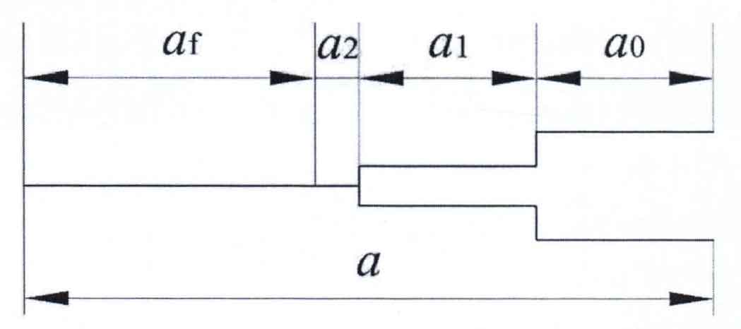
The crack length of the sample actually consists of 4mm original notch and 4mm induced notch α 1. 1mm prefabricated crack and fatigue crack are called four parts. The crack length is equal to the sum of the four parts, and the crack structure is shown in Figure 2.


