
The mathematical model of quasi hyperboloid gear tooth surface is derived by using parameters, and the position of tooth surface points and their unit normal vector are solved. According to the location of the topological points of the tooth surface and the assembly parameters of the gear pair, the 3D model of the quasi hyperboloid gear pair is generated using SolidWorks software.
After converting the mechanical parameter settings of the shaking table machine tool to the mechanical settings of the 6-axis CNC machine tool, calculate the workpiece machining coordinate position and plan the NC machining program, and perform actual machining on the gear. At the same time, the roll machining of the quasi hyperboloid gear surface is simulated by VERICUT software, and the simulation results and the theoretical gear surface error are analyzed.
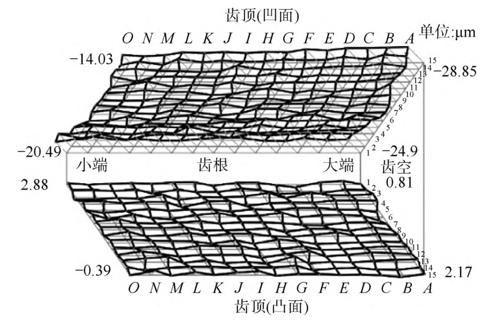
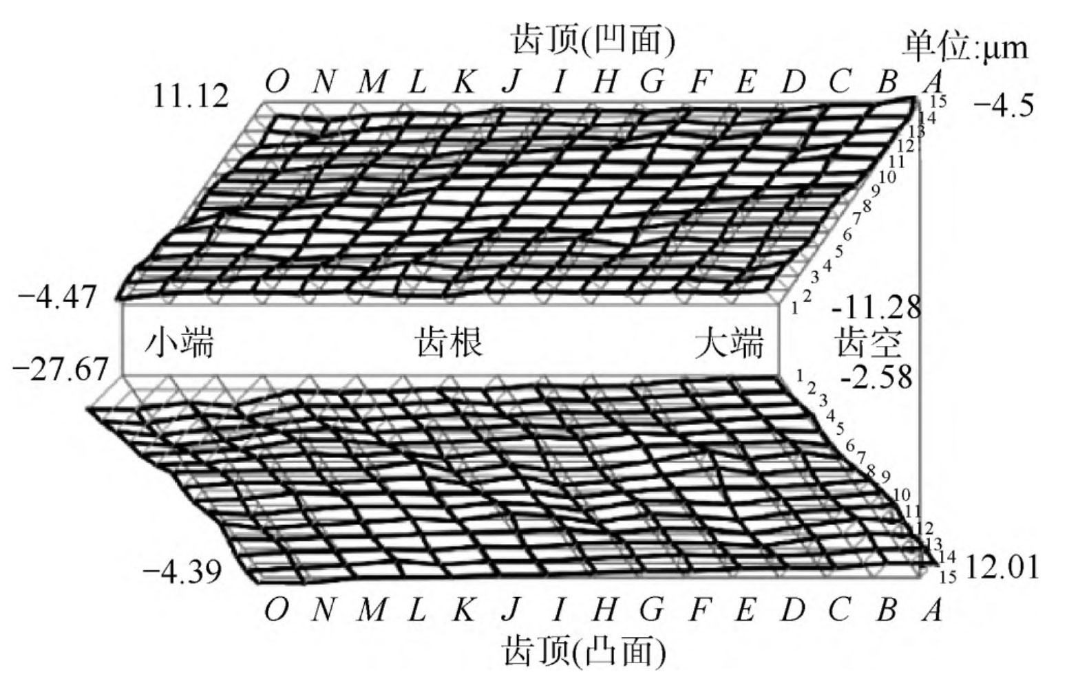
The analysis results indicate that the actual tooth thickness of the small gear is 7 509mm, tooth thickness error is+3 8 μ m; The actual tooth thickness of the large gear is 6 701mm, tooth thickness error is -39 62 μ m。 The tooth surface error diagrams are shown in Figure 8 and Figure 9, respectively.
Based on the general experience of VERICUT cutting simulation, the tooth surface point position error and tooth thickness error between the theoretical tooth surface and the cutting simulation gear are usually less than 50 μ m。 From Figures 8 and 9, it can be observed that the maximum error value of the tooth surface points of the small gear and the large gear is about 30 μ m. The tooth thickness error is+3 8 μ M and -39 62 μ m. The error values are all less than 50 μ m. This indicates that the mathematical model has high accuracy in implementing surface rolling full generation machining on a 6-axis CNC bevel gear cutting machine.