
Exploring hypoid gears involves understanding their theoretical principles and practical aspects in gear design and manufacturing. Let’s take a closer look at each stage:
- Theoretical Principles:
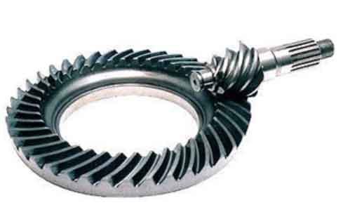
- Hypoid gears are a type of spiral bevel gears with non-intersecting, crossed axes.
- The gear teeth have a helical shape, resulting in a smooth meshing action and gradual tooth engagement, reducing noise and vibration.
- The gear ratio is determined by the number of teeth on the pinion and ring gear.
- The offset between the axes of the pinion and ring gear creates a hypoid offset, enabling compact drivetrain packaging.
- Design parameters, such as gear dimensions, pressure angles, tooth profiles, and tooth contact patterns, are crucial for optimizing performance, efficiency, and durability.
- Gear Design:
- The design process starts with defining the gear requirements, including torque capacity, speed, and application-specific factors.
- Computer-aided design (CAD) software is used to create a 3D model of the gear set, allowing for precise geometry definition and visualization.
- Finite element analysis (FEA) is often employed to simulate gear behavior under various loads, verifying its structural integrity and performance.
- Design iterations and optimization are conducted to achieve the desired gear performance, such as load capacity, efficiency, and noise reduction.
- Gear Manufacturing:
- Gear manufacturing involves several steps, including blank preparation, cutting, heat treatment, and finishing operations.
- Blank preparation: A suitable gear blank is selected, typically made of alloy steel. It is then cut or forged into the rough shape of the gear.
- Cutting: Gear cutting methods include generating (using gear hobbing or shaping) or form grinding. These processes create the gear tooth profiles and generate the desired helix angles.
- Heat treatment: The gear undergoes heat treatment processes, such as carburizing and quenching, to increase its surface hardness and improve wear resistance.
- Finishing: Operations like grinding, lapping, and honing are performed to achieve the required gear accuracy, surface finish, and noise reduction.
- Quality control: Gear measurement and inspection techniques, such as coordinate measuring machines (CMMs) and gear analyzers, are used to ensure the gear meets design specifications.
- Assembly and Testing:
- Once the gears are manufactured, they are assembled into the drivetrain system, including the differential and axle assembly.
- The assembled drivetrain undergoes testing to validate its performance, including load-carrying capacity, efficiency, noise, and vibration.
- Dynamometer testing and road testing are commonly conducted to evaluate the drivetrain’s behavior under various operating conditions.
Throughout the gear design and manufacturing process, collaboration between design engineers, manufacturing engineers, and quality control personnel is crucial to ensure the gear meets the desired performance, durability, and efficiency requirements. Continuous improvement efforts, advanced materials, and manufacturing techniques contribute to enhancing hypoid gear performance, optimizing the manufacturing process, and improving the overall drivetrain performance and fuel efficiency.