
Abstract
To obtain accurate modal parameters for the digital twin of a spiral bevel gear, modal tests were conducted on the gear to determine the modal frequencies, modal shapes, and frequency response functions in the free mode. The Auto Modal Assurance Criterion (Auto MAC) matrix was calculated, revealing low modal correlation among various orders, indicating the high accuracy of the modal shapes extracted from the modal test. Using the experimental modal frequencies as targets, the physical properties of the spiral bevel gear were refined, and modal simulations were performed to obtain the modal frequencies, modal shapes, and frequency response functions in the free mode. Comparing the simulation results with the modal test results, the maximum modal frequency deviation was found to be 1.235%. The Cross Modal Assurance Criterion (Cross MAC) matrix was calculated for the experimental and digital twin modal shapes, demonstrating good agreement between the digital twin modal shapes and the experimental modal shapes. The comparison of the experimental and simulated frequency response functions further validated the accuracy of the modal analysis of the digital twin. Modal simulation of the digital twin not only identified modal parameters that could not be tested due to experimental constraints but also allowed for the identification of modal parameters with relatively large experimental errors by comparing the experimental and simulated modal Cross MAC with the experimental modal Auto MAC. The comparative analysis between experiments and simulations showed that the spiral bevel gear digital twin model constructed in this study is accurate and can address the issues of incomplete and inaccurate measurements due to experimental constraints.
1. Introduction
Spiral bevel gears are crucial components for power and motion transmission, and their dynamic characteristics, strength, lifespan, and reliability have significant impacts on the overall transmission system. For instance, when the gear meshing frequency approaches its natural frequency, severe vibrations and noise can occur. Especially in the aviation sector, transmission systems are continuously evolving towards lighter weight, higher load capacity, and faster speeds, exacerbating issues related to gear meshing vibrations and noise. Modal analysis is a primary method for studying structural dynamics, enabling the determination of gear dynamic properties and more accurate prediction of the real-world operating conditions and performance of spiral bevel gears. Furthermore, modal analysis results can guide gear redesign, assist designers in identifying structural weaknesses, perform structural dynamic modifications, and predict changes in dynamic characteristics resulting from structural alterations.
Modal analysis of spiral bevel gears using the finite element method (FEM) involves defining approximate physical properties, making it difficult to accurately assess the modal parameters obtained through simulation. Experimental testing, on the other hand, may suffer from incomplete measurements. Moreover, the separation of physical entities from finite element models makes it challenging to correlate experimental modal data with finite element models. Digital twins represent digital mirror images of real physical entities. Constructing a digital twin model involves creating a digital representation of the attributes, methods, and behaviors of a physical entity or process in a digital space, enabling precise simulation and mapping of the physical entity’s morphology and performance in a virtual space. The primary task in implementing digital twins is to create an accurate digital twin model of the application object, which can then be used to effectively assess mechanical properties, service properties, and predict lifespan.
Spiral bevel gears exhibit a cyclically symmetric structure with tooth surfaces that form spatial curves. Accurate digital twin modeling of spiral bevel gears requires precise geometric shapes and structures, combined with accurate material physical properties, to accurately map the dynamic characteristics of the physical entity. This study proposes a method that combines experiments and simulations. Based on constructing an accurate geometric model, the physical properties of the spiral bevel gear are refined to establish an accurate digital twin model. Through simulation analysis, the modal frequencies, modal shapes, and frequency response functions in the free mode are obtained, and a quantitative correlation analysis is performed between the simulation and experimental modal analysis results to verify the accuracy of the modal analysis.
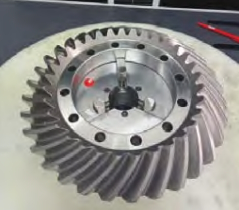
2. Modal Testing of Spiral Bevel Gear
2.1 Modal Test Plan
The modal test was conducted on the large gear of a spiral bevel gear pair. Table 1 lists the basic parameters of the spiral bevel gear pair, and the gear tooth surface coordinates detected at the gear inspection center, which were used to construct an accurate geometric model of the gear.
Table 1: Basic Parameters of the Large Gear of the Spiral Bevel Gear Pair
| Parameter | Large Gear |
|---|---|
| Number of Teeth | 33 |
| Module | 8.4848 |
| Helical Direction | Right-handed |
| Face Width (mm) | 46 |
| Pressure Angle (°) | 20 |
| Helix Angle (°) | 35 |
| Pitch Cone Angle (°) | 51.767 |
| Face Cone Angle (°) | 54.193 |
| Root Cone Angle (°) | 48.585 |
| Midpoint Cone Distance (mm) | 155.23 |
| Addendum Height (mm) | 5.939 |
| Dedendum Height (mm) | 9.955 |
Free modal testing of spiral bevel gears implies testing without any constraints. However, it is impractical to completely suspend the gear in the air. Therefore, during the test, the gear was suspended using 2 m of elastic nylon rope to achieve a free boundary condition. The moving force hammer method was employed to measure the modal parameters and modal shapes of the large gear. Excitation points and response points were evenly distributed on the back of the gear. Four accelerometers were installed at the measurement points, with 132 measurement points planned for the large gear. the measurement point locations and numbers. Each measurement point was struck three times, and the average values were recorded.
2.2 Experimental Modal Analysis
The force hammer and vibration response signals were collected using a signal acquisition instrument. the time-domain signal of the hammer excitation force, and the time-domain and frequency-domain signals, respectively, of the vibration acceleration at measurement point 38.
Through experimental testing, the modal frequencies and modal shapes in the free mode were obtained. Table 2 lists the experimentally measured modal frequencies and damping ratios of the large gear.
Table 2: Experimental Modal Frequencies and Damping Ratios of the Large Gear
| Modal Order | Frequency (Hz) | Damping Ratio (%) |
|---|---|---|
| 1 | 1436.3 | 0.098 |
| 2 | 1441.1 | 0.083 |
| 5 | 3400.5 | 0.112 |
| 6 | 3700.5 | 0.086 |
| 7 | 3700.7 | 0.094 |
| 8 | 5195.8 | 0.063 |
| 9 | 5204.0 | 0.295 |
| 12 | 6393.0 | 0.070 |
| 13 | 6403.7 | 0.029 |
| 15 | 8653.2 | 0.140 |
| 16 | 8686.5 | 0.101 |
| 17 | 9267.0 | 0.093 |
| 18 | 9268.4 | 0.073 |
Due to the one-dimensional nature of vibration accelerometers, they primarily detect axial vibration signals of the gear. Among the first 18 modal shapes, the 3rd, 4th, 9th, 10th, 11th, and 14th orders primarily exhibit radial vibrations, making it impossible to detect their modal shapes and frequencies. the experimental modal shapes corresponding to Table 2.
The Modal Assurance Criterion (MAC) value is used to evaluate the geometric correlation between modal shape vectors of different orders. The MAC between two modal shape vectors {φ}_r and {φ}_s is defined as:
textMAC(r,s)=φr⋅φr×φs⋅φsφr⋅φs
where r and s represent the modal orders.
In the MAC matrix, the diagonal elements are the dot products of each modal shape vector with itself, resulting in MAC values of 1. The off-diagonal elements are the dot products of different modal shapes, and their MAC values should be 0. An MAC value of 0 indicates orthogonality between two modal shape vectors; an MAC value close to 0 indicates low correlation between the two modal shape vectors; and an MAC value close to 1 indicates high similarity between the two modal shape vectors. the Auto-MAC matrix for the experimental modal shapes of the large gear. the diagonal elements are mostly 1; off-diagonally, the values between the 15th and 1st orders are 0.0737, and those between the 16th and 2nd orders are 0.0558, with the rest being nearly 0. This low correlation among various modal orders proves the accuracy of the modal shapes extracted from the modal test.
3. Refinement of Physical Properties of Spiral Bevel Gear
Based on the experimental results, the physical properties of the spiral bevel gear digital twin, such as elastic modulus, density, and Poisson’s ratio, were refined to obtain a more accurate digital twin model.
3.1 Modal Simulation Boundary Conditions of Spiral Bevel Gear
Using the basic and processing parameters of the spiral bevel gear, a precise finite element model of the large gear was established based on tooth surface inspection. The modal test measured free modes, and the sensor data captured the vibration acceleration response under unconstrained conditions. To more accurately simulate the experimental boundary conditions, zero-dimensional spring elements (e.g., CBUSH elements) combined with one-dimensional connection elements (e.g., RBE3 elements) were used to simulate the nylon rope suspension. The zero-dimensional spring elements have no mass and provide only in six degrees of freedom, simulating the nylon rope used for suspension. The RBE3 elements reduce the influence of the introduced by the CBUSH elements on the modal frequencies. Modal analysis was performed on the finite element model of the spiral bevel gear to calculate the modal frequencies.
3.2 Refinement of Physical Properties
With the absolute minimum difference between the simulated and experimental modal frequencies as the objective function, the physical properties of the spiral bevel gear, including elastic modulus E, Poisson’s ratio μ, and density ρ, were refined. The response surface methodology (RSM) is a statistical method that seeks optimal parameters by analyzing multiple quadratic regression equations to solve multivariable problems. The optimal material parameter combination was determined using the response surface method with a “three-factor, five-level” central composite design. Since the modal test detected 13 modal frequencies, the optimization objective function was:
mini=1∑13∣Yi−Y^i(E,ρ,μ)∣
where Y_i is the i-th experimental modal frequency, and \hat{Y}_i(E, \rho, μ) is the i-th predicted frequency value from the response surface.
After optimization, the refined physical properties were: elastic modulus E = 226,048 N/mm²; density ρ = 8,399 kg/m³; and Poisson’s ratio μ = 0.256.
4. Validation and Assessment of the Digital Twin Model
4.1 Comparison and Analysis of Modal Frequencies
Table 3 compares the experimental and simulated modal frequencies of the spiral bevel gear. Due to the cyclically symmetric structure of bevel gears, there are multiple pairs of closely spaced repeated roots. Among the first 18 modal frequencies, the maximum relative error occurs at the 15th order. The 15th and 16th orders are repeated root modes, and theoretically, their modal frequencies should be identical. However, there is a significant frequency difference between the 15th and 16th experimental modal frequencies, with a relative error of 1.235% for the 15th order and 0.85% for the 16th order. This frequency difference is likely due to factors such as the weight of the sensors during measurement, which may have partially disrupted the cyclical symmetry. The consistency between the experimental and simulated modal frequencies indicates that refining the material physical properties of the bevel gear can effectively extract its modal frequencies.
Table 3: Comparison of Experimental and Simulated Modal Frequencies of the Spiral Bevel Gear
| Modal Order | Experimental Frequency (Hz) | Simulated Frequency (Hz) | Relative Error (%) |
|---|---|---|---|
| 1 | 1436.3 | 1441.8 | 0.383 |
| 2 | 1441.1 | 1441.8 | 0.049 |
| 3 | – | 2559.0 | – |
| 4 | – | 2559.0 | – |
| 5 | 3400.5 | 3400.7 | 0.000 |
| 6 | 3700.6 | 3700.9 | 0.008 |
| 7 | 3700.7 | 3700.9 | 0.003 |
| 8 | 5195.8 | 5232.5 | 0.706 |
| 9 | 5204.0 | 5232.5 | 0.548 |
| 10 | – | 6347.1 | – |
| 11 | – | 6347.1 | – |
| 12 | 6393.0 | 6398.5 | 0.085 |
| 13 | 6403.7 | 6398.5 | -0.070 |
| 14 | – | 7229.0 | – |
| 15 | 8653.1 | 8760.0 | 1.235 |
| 16 | 8686.5 | 8760.0 | 0.850 |
| 17 | 9267.0 | 9267.0 | 0.000 |
| 18 | 9268.4 | 9267.0 | -0.015 |
4.2 Comparison and Analysis of Experimental and Simulated Modal Shapes
The simulated modal shapes for each order. Comparison with the experimental modal shapes reveals that the simulated modal shapes are identical to the experimentally measured ones. Structures with repeated root modes exhibit identical modal shapes but with angular differences. The consistency between the experimental and simulated modal shapes indicates that the constructed digital twin of the spiral bevel gear can match the modal characteristics of its physical entity.
The consistency between the experimental and simulated modal shapes for each order was evaluated using the Cross Modal Assurance Criterion (Cross MAC) matrix, defined as:
textCrossMAC(rE,sF)=φrE⋅φrE×φsF⋅φsFφrE⋅φsF
where {φ}{r_E} represents the r-th experimental modal shape, and {φ}{s_F} represents the s-th simulated modal shape.
A Cross MAC value close to 0 indicates orthogonal modal shapes, while a value close to 1 indicates high similarity. the Cross MAC matrix for the experimental and simulated modal shapes. The Cross MAC values on the main diagonal are close to 1, and those off-diagonal are close to 0, indicating good consistency between the simulated and experimental modal analysis results. This consistency is particularly evident for repeated root modes such as the 1st and 2nd, 6th and 7th, 8th and 9th, and 12th and 13th orders.
Off-diagonally, the Cross MAC value between the 15th experimental and 1st simulated modal shapes is 0.0603, and that between the 16th experimental and 2nd simulated modal shapes is 0.0454. Comparing these values with the Auto MAC matrix for the experimental modal shapes.