
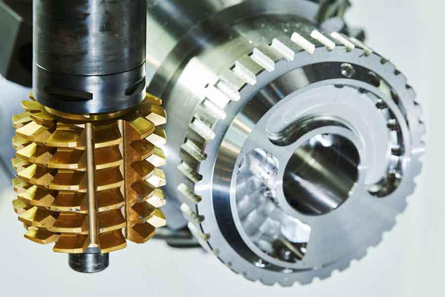
Face gear transmission offers exceptional advantages for aerospace applications, including lightweight construction, insensitivity to axial misalignment, and high load capacity. To enhance manufacturing efficiency, we investigate gear hobbing using spherical hobs – a method enabling continuous cutting motion that significantly reduces production time compared to shaping. This approach addresses the limitations of conventional hobs that produce unacceptable deviations in face gear tooth geometry.
The tooth surface of a face gear is generated through the kinematic simulation of a cylindrical pinion shaper. For a shaper with base radius \(r_{bs}\) and pressure angle \(\alpha\), the involute tooth profile coordinates in the shaper coordinate system \(S_s\) are:
$$r_s(u_s, \theta_s) =
\begin{bmatrix}
\pm r_{bs} \left[ \sin(\theta_{0s} + \theta_s) – \theta_s \cos(\theta_{0s} + \theta_s) \right] \\
– r_{bs} \left[ \cos(\theta_{0s} + \theta_s) + \theta_s \sin(\theta_{0s} + \theta_s) \right] \\
u_s
\end{bmatrix}$$
where \(\theta_{0s}\) defines the involute starting angle, \(\theta_s\) is the involute parameter, and \(u_s\) represents the tooth width direction. The \(\pm\) corresponds to left/right flanks.
Coordinate transformation between the shaper \(S_s\) and face gear \(S_2\) systems during meshing yields the face gear tooth surface:
$$r_2(u_s, \theta_s, \phi_s) = M_{2s}(\phi_s) r_s(u_s, \theta_s)$$
with the meshing constraint:
$$n_s \cdot v_s^{(s2)} = 0$$
where \(M_{2s}\) is the transformation matrix, \(n_s\) is the shaper tooth normal vector, and \(v_s^{(s2)}\) is the relative velocity vector.
Spherical Hob Fundamental Design
Conventional hobs generate significant deviations in face gears due to their straight-line generating surfaces. The spherical hob concept addresses this by simulating the cylindrical shaper’s action through a specialized worm geometry. This worm’s transverse sections replicate the shaper’s involute profile across a spherical surface, enabling accurate conjugate motion.
The spherical worm surface derivation begins with the base sphere concept. Defining coordinate systems: \(S_0\) (fixed), \(S_{n0}\) (auxiliary fixed, rotated by \(\lambda\)), \(S_w\) (worm rotation), and \(S_n\) (cutter rotation). The coordinate transformations are:
$$M_{w,0} = \begin{bmatrix} \cos\phi_w & -\sin\phi_w & 0 & 0 \\ \sin\phi_w & \cos\phi_w & 0 & 0 \\ 0 & 0 & 1 & 0 \\ 0 & 0 & 0 & 1 \end{bmatrix}, \quad M_{0,n0} = \begin{bmatrix} 1 & 0 & 0 & 0 \\ 0 & \cos\lambda & -\sin\lambda & 0 \\ 0 & \sin\lambda & \cos\lambda & 0 \\ 0 & 0 & 0 & 1 \end{bmatrix}$$
$$M_{n0,n} = \begin{bmatrix} \cos\phi_0 & 0 & -\sin\phi_0 & 0 \\ 0 & 1 & 0 & 0 \\ \sin\phi_0 & 0 & \cos\phi_0 & 0 \\ 0 & 0 & 0 & 1 \end{bmatrix}$$
The worm surface equation in \(S_w\) is derived through coordinate transformation of the involute profile:
$$r_w(\phi_w, \theta) = M_{w,0} M_{0,n0} M_{n0,n} \begin{bmatrix} r_b \left[ \cos(\theta_0 + \theta) + \theta \sin(\theta_0 + \theta) \right] \\ 0 \\ \pm r_b \left[ \sin(\theta_0 + \theta) – \theta \cos(\theta_0 + \theta) \right] \\ 1 \end{bmatrix}$$
which expands to:
$$r_w(\phi_w, \theta) = \begin{bmatrix}
r_b \left[ \cos\phi_w (\cos\xi \pm \theta\sin\xi) + \sin\lambda \sin\phi_w (\sin\xi \mp \theta\cos\xi) \right] \\
r_b \left[ \sin\phi_w (\cos\xi \pm \theta\sin\xi) – \sin\lambda \cos\phi_w (\sin\xi \mp \theta\cos\xi) \right] \\
r_b \cos\lambda \left( \sin\xi \mp \theta\cos\xi \right)
\end{bmatrix}$$
where \(\xi = \phi_0 \pm (\theta_0 + \theta)\). The nominal helix angle \(\lambda_0\) is critical for hob installation alignment:
$$\sin\lambda_0 = \frac{1}{N_0}$$
where \(N_0\) is the virtual shaper’s tooth count. This angle ensures proper meshing kinematics during gear hobbing.
Hobbing Kinematics and Tooth Generation
During face gear gear hobbing, two synchronized motions occur: the hob’s rotation \(\phi_h\) and the face gear’s rotation \(\phi_2\), maintained at a fixed ratio \(\phi_2/\phi_h = N_h/N_2\) (\(N_h\) = hob starts, typically 1). Simultaneously, radial feed \(l\) positions the hob relative to the face gear blank. The coordinate transformation from hob \(S_h\) to face gear \(S_2\) is:
$$M_{2,h}(\phi_h, l) = \begin{bmatrix}
-\sin\phi_h \cos(\phi_2 + \lambda_0) & -\cos\phi_h \cos(\phi_2 + \lambda_0) & -\sin(\phi_2 + \lambda_0) & l \cos\phi_2 \\
-\sin\phi_h \sin(\phi_2 + \lambda_0) & -\cos\phi_h \sin(\phi_2 + \lambda_0) & \cos(\phi_2 + \lambda_0) & l \sin\phi_2 \\
-\cos\phi_h & \sin\phi_h & 0 & 0 \\
0 & 0 & 0 & 1
\end{bmatrix}$$
The generated face gear surface requires solving the position vector and dual meshing conditions:
$$r_2(\phi_h, l, \phi_w, \theta) = M_{2,h}(\phi_h, l) r_w(\phi_w, \theta)$$
$$f(\phi_h, l, \phi_w, \theta) = n_h \cdot v_h^{(h2,\phi_h)} = 0$$
$$g(\phi_h, l, \phi_w, \theta) = n_h \cdot v_h^{(h2,l)} = 0$$
where \(v_h^{(h2,\phi_h)}\) and \(v_h^{(h2,l)}\) are relative velocity vectors for rotational and feed motions, respectively, and \(n_h\) is the hob tooth normal vector.
Simulation and Experimental Verification
We validated the spherical hob through VERICUT simulations and physical machining trials. Two face gear specifications were examined:
| Parameter | Case 1 | Case 2 |
|---|---|---|
| Face Gear Teeth | 42 | 160 |
| Pinion Teeth | 23 | 26 |
| Module (mm) | 3.5 | 1.0583 |
| Pressure Angle (°) | 25 | 20 |
| Tooth Length (mm) | 15 | 5 |
| Hob Helix Angle λ₀ (°) | 2.492 | 2.2 |
VERICUT simulations incorporated synchronized rotational motion via specialized G-code: CGTECH_MACRO "GearModeOnOff" "1". The comparative analysis revealed exceptional geometric fidelity:
| Performance Metric | Case 1 | Case 2 |
|---|---|---|
| Max Deviation from Shaped Gear (μm) | 0.01 | 0.005 |
| Root Cut Simulation | Visible | N/A |
| Tooth Tip Sharpening | Observed | N/A |
Physical gear hobbing of Case 2 employed a custom spherical hob on a CNC face gear hobbing machine. Coordinate measuring machine (CMM) inspection quantified deviations across the tooth surface. The maximum observed error was -44.3 μm, attributable to hob manufacturing tolerances, machine tool positioning errors, and setup alignment inaccuracies.
Conclusion
This research establishes spherical hobbing as a viable high-efficiency method for face gear manufacturing. The mathematical framework enables precise spherical hob design, with the derived worm surface equations ensuring geometrically accurate tooth generation. VERICUT simulations confirmed negligible deviation (≤0.01 μm) from theoretical shapes, while physical trials demonstrated practical feasibility despite error sources inherent to physical systems. For aerospace applications requiring hardened gears, this gear hobbing process significantly reduces roughing cycle times before final grinding. Future work will optimize hob manufacturing techniques to minimize tooth deviation and enhance process robustness for industrial implementation.