
Abstract
Design methodology for hypoid gear operating under low crossed shaft angles. By leveraging the instantaneous axis of uniparted hyperboloids, we derive spatial pitch cone relationships and establish a mesh behavior control strategy that ensures smooth root transitions. Finite element analysis (FEA) is employed to investigate the influence of external loads on contact stress, bending stress, and transmission error. A prototype validated the stability of hypoid gear in extreme low-shaft-angle conditions.
1. Introduction
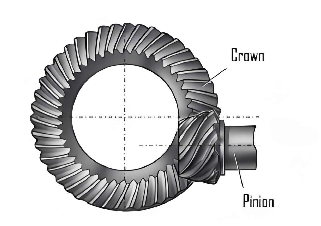
Hypoid gear is pivotal in power transmission systems requiring non-parallel, non-intersecting axes. Their ability to handle high torque and provide smooth operation makes them indispensable in automotive, marine, and aerospace applications. However, traditional hypoid gear design methodologies falter under low crossed shaft angles (Σ < 20°), where extreme geometric scaling (e.g., reduced offset distance E) complicates tooth surface generation and meshing behavior.
Existing solutions, such as tapered involute gears, suffer from limited adjustability and sensitivity to misalignment. In contrast, hypoid gear offer superior contact ratios, customizable meshing properties, and unrestricted pitch cone angles. This paper addresses the gap in low-shaft-angle hypoid gear design by:
- Deriving geometric relationships for pitch cones based on instantaneous hyperboloid axes.
- Optimizing machine-tool settings using a modified local synthesis method.
- Validating meshing performance under varying loads via FEA.
- Prototyping and testing a hypoid gear pair with Σ = 15°.
2. Geometric Design of Hypoid Gear with Low Crossed Shaft Angles
2.1 Instantaneous Axis and Pitch Cone Relationships
The relative motion between crossed axes is modeled as a screw motion along the instantaneous axis (IA). For two hyperboloids rotating about skewed axes (Figure 1), the IA coordinates in the global frame S_f are:xfyfzf=1−2m21cosΣ+m212Em21(cosΣ−m21)=−usinβ=ucosβ
where u is a parametric variable, m_{21} is the angular velocity ratio, and β is the IA inclination angle.
By converting IA coordinates to pinion and gear reference frames (Equations 3–4), we establish pitch cone parameters (Figure 2). Key geometric relationships include:
- Spiral Angle Difference:cosβm12=tanγm1tanγm2+cosγm1cosγm2cosΣ
- Velocity Ratio:i12=rm1cosβm1rm2cosβm2
- Offset Distance:E=sinΣsinβm12(rm1cosγm2+rm2cosγm1)
2.2 Design Workflow
The iterative design process (Figure 3) ensures convergence of offset distance E and tool radius r_{co}. Key steps include:
- Loop A: Adjusting gear offset angle ε_m to match theoretical E.
- Loop B: Optimizing root curvature and machine-tool settings.
Table 1: Key Geometric Parameters of Hypoid Gear
| Parameter | Pinion (i=1) | Gear (i=2) |
|---|---|---|
| Teeth Count (N_i) | 29 | 37 |
| Shaft Angle (Σ) | 15° | 15° |
| Offset Distance (E) | 25 mm | 25 mm |
| Pitch Cone Angle (γ_mi) | 7.34° | 6.89° |
| Spiral Angle (β_mi) | 24.75° | 20.00° |
3. Local Synthesis Optimization for Low-Shaft-Angle Hypoid Gear
3.1 Machine-Tool Settings
Hypoid gear manufacturing involves complex machine adjustments (Table 2). For the gear (face-milling) and pinion (generating), critical parameters include:
- Gear: Radial setting (S_{r2}), angular setting (Q_{r2}), root angle (M_{r2}).
- Pinion: Tilt angle (T_{rli}), swivel angle (W_{rli}), ratio (V_{rli}).
Table 2: Machine-Tool Settings for Gear and Pinion
| Parameter | Gear (Concave) | Pinion (Concave) | Pinion (Convex) |
|---|---|---|---|
| Radial Setting | 341.91 mm | 104.61 mm | 96.04 mm |
| Tilt Angle | – | -81.62° | -82.62° |
| Machine Root Angle | 6.22° | -73.52° | -74.60° |
3.2 Root Transition Smoothing
To eliminate root step-overs (Figure 4), we iteratively adjust the machine root angles (M_{rli}) to align projected root lines (C_1C_n, V_1V_n) with the axis. The convergence criterion ensures:γmc≈γmv
4. Meshing Behavior Analysis Under External Loads
4.1 Tooth Contact Analysis (TCA)
Discretizing tooth surfaces into m×n grids (Figure 5), we calculate contact points where inter-tooth distance d_{pw} < 6.35 μm. Results show:
- Contact ellipses align with preset parameters (L_{ce} = 8 mm, θ_{ce} = 80°).
- Transmission error (TE) peaks at -15 arcsec, matching design goals.
Table 3: Preset vs. Actual Meshing Parameters
| Parameter | Preset Value | TCA Result |
|---|---|---|
| Contact Ellipse Length | 8 mm | 8.2 mm |
| TE Peak-to-Peak | -12 arcsec | -14.7 arcsec |
4.2 Loaded Tooth Contact Analysis (LTCA)
FEA models (Figure 6) reveal:
- Contact Stress: Increases linearly with torque but triggers edge contact above 100 N·m (Figure 7).
- Bending Stress: Peaks at the root center, rising proportionally to load (Figure 8).
- Transmission Error: TE amplitude decreases initially, then rises due to tooth deflection (Figure 9).
Table 4: Stress and TE Under Varying Loads
| Torque (N·m) | Max Contact Stress (MPa) | Max Bending Stress (MPa) | TE Peak-to-Peak (arcsec) |
|---|---|---|---|
| 50 | 820 | 310 | -12.1 |
| 100 | 1,480 | 590 | -14.9 |
| 150 | 2,210* | 870 | -18.3 |
| *Edge contact observed. |
5. Prototype Validation
A 3D-printed hypoid gear pair (Figure 10) and a 15° crossed-axis transmission prototype (Figure 11) confirm:
- Smooth meshing with no root interference.
- Stable operation under 0–100 N·m loads.
- TE and contact patterns align with simulations.
6. Conclusion
- The proposed geometric design methodology enables precise control of hypoid gear parameters under low shaft angles.
- Modified local synthesis eliminates root step-overs, ensuring manufacturing feasibility.
- Hypoid gear exhibit load-dependent TE and stress profiles, necessitating careful torque calibration.
- Prototype validation confirms the methodology’s robustness for extreme geometric conditions.
Future Work: Extending this methodology to ultra-low shaft angles (Σ < 10°) and exploring additive manufacturing for high-strength hypoid gear.