
In modern precision engineering, the harmonic drive gear system has become indispensable due to its unique advantages such as high reduction ratios, compact design, and zero-backlash characteristics. These gears are widely used in robotics, aerospace, medical devices, and industrial automation. However, the traditional manufacturing methods for harmonic drive gears, which typically involve forging, turning, and gear cutting (e.g., hobbing or shaping), face significant limitations. These processes are inefficient, costly, and struggle to achieve the high precision required for advanced applications, especially given the small module (often less than 1 mm) and high tooth count of harmonic drive gears. To address these challenges, cold-rolling has emerged as a promising alternative for mass production of harmonic drive gears. This process enhances material utilization, improves surface integrity, and increases fatigue strength by maintaining continuous metal fiber flow. Nonetheless, achieving high tooth accuracy in cold-rolled harmonic drive gears remains a complex task, primarily due to the variable pitch nature of the rolling process. In this article, I will analyze the key factors influencing the tooth accuracy of cold-rolled harmonic drive gears from a systemic perspective, focusing on the variable circumferential pitch phenomenon, and provide theoretical insights for improving rolling precision.
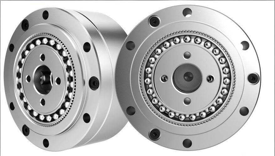
The cold-rolling process for harmonic drive gears involves forming teeth on a gear blank through plastic deformation at room temperature. Typically, a two-roll setup is used, where two rolling tools (rolls) synchronously engage with the gear blank. The rolls and the blank perform a generating motion while the rolls radially feed into the blank. As the rolls press into the blank, the material plastically deforms and flows to form the tooth profile. This method is efficient and suitable for high-volume production of harmonic drive gears. The fundamental principle can be described by the generating motion between the roll and the blank, analogous to gear meshing without backlash. The roll, with a defined tooth profile, progressively impresses its shape onto the blank over multiple passes. The success of this process hinges on precise control over various parameters to ensure accurate tooth formation, particularly for harmonic drive gears with their thin-walled and high-tooth-count characteristics.
A critical aspect of cold-rolling harmonic drive gears is the variable circumferential pitch during the process. Unlike conventional gear cutting, where the pitch is fixed, cold-rolling involves a dynamic change in the pitch as the rolling proceeds. This phenomenon occurs because the pitch circle diameter between the roll and the blank continuously changes during the rolling stages. The entire process can be divided into three distinct phases: the initial engagement phase, the forming phase, and the finishing phase. In the initial phase, the roll’s tip diameter contacts the outer diameter of the blank, and the roll’s tip circumferential pitch is transferred to the blank to create initial grooves. The circumferential pitch at this stage is given by:
$$ p_a = \frac{\pi d_a}{z_2} $$
where \( p_a \) is the initial pitch, \( d_a \) is the outer diameter of the blank, and \( z_2 \) is the number of teeth on the harmonic drive gear. During the forming phase, as the roll radially feeds inward, the instantaneous pitch circle diameter changes, leading to a variable pitch:
$$ p_i = \frac{\pi d_{2i}}{z_2} $$
where \( p_i \) is the instantaneous pitch, and \( d_{2i} \) is the changing pitch circle diameter of the blank. Finally, in the finishing phase, the roll and blank achieve pure rolling at the reference pitch circle (equivalent to the gear’s standard pitch diameter), with the pitch becoming:
$$ p_f = \frac{\pi d_{20}}{z_2} $$
where \( p_f \) is the final pitch, and \( d_{20} \) is the standard pitch diameter of the harmonic drive gear. This variable pitch mechanism necessitates precise dynamic indexing to avoid errors such as multi-toothing, missing teeth, or irregular tooth spacing. Understanding and controlling this variation is essential for achieving high accuracy in cold-rolled harmonic drive gears.
The tooth accuracy of cold-rolled harmonic drive gears is influenced by multiple factors within the manufacturing system, including the gear blank dimensions, roll geometry, and the motion control of the rolling equipment. I will now analyze these factors in detail, emphasizing their impact on the variable pitch process and overall precision.
Influence of Gear Blank Diameter
The diameter of the gear blank is a fundamental parameter that directly affects the initial indexing and final tooth geometry of the harmonic drive gear. Based on the principle of volume constancy before and after rolling, the blank diameter must be calculated precisely to ensure proper material flow and avoid defects. If the blank diameter is too small, insufficient material will lead to incomplete tooth profiles and undersized tip diameters. Conversely, if it is too large, excess material may cause flash or burrs, degrading the gear quality. Moreover, in the initial engagement phase, the blank’s outer diameter determines the first pitch division. An incorrect diameter can result in indexing errors, manifesting as pitch deviations across the harmonic drive gear. The relationship between the blank diameter \( d_k \) and the roll’s tip diameter \( d_{a1} \) for proper indexing can be derived from the gear meshing condition:
$$ \frac{d_{a1}}{z_1} = \frac{d_k}{z_2} $$
where \( z_1 \) is the number of teeth on the roll. This equation ensures that the roll’s tip pitch matches the blank’s circumferential pitch at the start, facilitating accurate initial tooth spacing for the harmonic drive gear. Deviations from this condition can cause cumulative pitch errors throughout the rolling process. Therefore, optimizing the blank diameter is crucial for the success of cold-rolling harmonic drive gears.
| Parameter | Symbol | Influence on Harmonic Drive Gear Accuracy |
|---|---|---|
| Blank Outer Diameter | \( d_k \) | Determines initial pitch division; affects material flow and tooth completeness. |
| Roll Tip Diameter | \( d_{a1} \) | Must satisfy indexing condition with blank diameter to avoid pitch errors. |
| Standard Pitch Diameter | \( d_{20} \) | Target for final pitch; deviations indicate inaccuracies in rolling process. |
Influence of Roll Geometry and Parameters
The roll tool is a critical component in cold-rolling harmonic drive gears. Its geometric parameters, such as module, pressure angle, and tooth profile, must match those of the harmonic drive gear being produced. To ensure longevity and accuracy, the roll diameter should be maximized within the machine’s constraints, often leading to a high tooth count on the roll. However, the most significant challenge lies in accommodating the variable pitch requirement during rolling. Ideally, the roll should have a variable circumferential pitch along its circumference to match the changing pitch circle diameters. However, this is impractical with current technology for gear-shaped tools, as the roll repeatedly contacts the blank over multiple rotations. As an alternative, a rack tool with linearly adjustable pitch could be used, but for rolling harmonic drive gears, a gear-shaped roll is typically employed. This necessitates motion compensation through forced synchronization, where the relative speeds of the roll and blank are dynamically adjusted. The roll’s main parameters must satisfy the following conditions for proper engagement with the harmonic drive gear blank:
$$ m_1 = m_2, \quad \alpha_1 = \alpha_2 $$
where \( m_1 \) and \( m_2 \) are the modules of the roll and harmonic drive gear, respectively, and \( \alpha_1 \) and \( \alpha_2 \) are their pressure angles. Additionally, the roll often requires negative profile shifting to accommodate the material flow and ensure correct tooth depth for the harmonic drive gear. The dynamic indexing requirement means that the roll’s effective pitch must change during rolling, which is achieved by controlling the rotational speeds rather than modifying the roll geometry. This highlights the interplay between tool design and process control in manufacturing precise harmonic drive gears.
Influence of Rolling Equipment and Motion Control
To achieve high precision in cold-rolled harmonic drive gears, modern rolling machines employ numerical servo control for forced synchronization. This approach allows real-time adjustment of the workpiece speed to compensate for the variable pitch effect. A typical cold-rolling machine for harmonic drive gears includes three main axes of motion: the rotation of the rolls (C2 axis), the rotation of the workpiece (C1 axis), and the radial feed of the rolls (X axis). These axes are interconnected through a CNC system to execute the generating and feeding motions precisely. During rolling, the roll speed \( n_1 \) is kept constant, while the workpiece speed \( n_2 \) is varied based on the instantaneous pitch circle diameter. The relationship is governed by the fundamental rolling condition:
$$ n_{2i} \cdot d_{2i} = \text{constant} $$
where \( n_{2i} \) and \( d_{2i} \) are the instantaneous rotational speed and pitch circle diameter of the harmonic drive gear blank, respectively. In the initial engagement phase, the workpiece speed is calculated as:
$$ n_2 = n_1 \cdot \frac{d_{a1}}{d_k} $$
During the finishing phase, the speed ratio is given by:
$$ \frac{n_1}{n_2} = \frac{z_2}{z_1} $$
And in the forming phase, the workpiece speed is dynamically adjusted as:
$$ n_{2i} = n_1 \cdot \frac{d_{a1}}{d_{2i}} $$
This speed compensation ensures that the circumferential pitch remains consistent with the required tooth spacing at each stage, mitigating errors due to the variable pitch phenomenon. Additionally, the radial feed position of the rolls must be controlled with high accuracy to manage the material deformation and achieve the final tooth dimensions for the harmonic drive gear. The integration of precise motion control with robust machine structure is vital for minimizing deviations and enhancing the overall accuracy of cold-rolled harmonic drive gears.
| Rolling Phase | Pitch Circle Diameter | Circumferential Pitch | Workpiece Speed Adjustment |
|---|---|---|---|
| Initial Engagement | \( d_k \) (blank outer diameter) | \( p_a = \pi d_k / z_2 \) | \( n_2 = n_1 \cdot d_{a1} / d_k \) |
| Forming Phase | \( d_{2i} \) (variable) | \( p_i = \pi d_{2i} / z_2 \) | \( n_{2i} = n_1 \cdot d_{a1} / d_{2i} \) |
| Finishing Phase | \( d_{20} \) (standard pitch diameter) | \( p_f = \pi d_{20} / z_2 \) | \( n_2 = n_1 \cdot z_1 / z_2 \) |
Mathematical Modeling of Variable Pitch in Cold-Rolling
To further understand the impact of variable pitch on harmonic drive gear accuracy, I developed a mathematical model that describes the pitch variation throughout the rolling process. This model considers the geometric and kinematic relationships between the roll and the harmonic drive gear blank. The instantaneous pitch circle diameter \( d_{2i} \) can be expressed as a function of the radial feed \( \Delta r \), which is the distance the roll has penetrated into the blank:
$$ d_{2i} = d_k – 2 \cdot \Delta r \cdot f(\theta) $$
where \( f(\theta) \) is a function accounting for the material flow and deformation geometry, and \( \theta \) represents the angular position. The circumferential pitch at any moment is then:
$$ p_i = \frac{\pi (d_k – 2 \cdot \Delta r \cdot f(\theta))}{z_2} $$
The cumulative pitch error \( E_p \) over one revolution of the harmonic drive gear can be integrated as:
$$ E_p = \sum_{i=1}^{z_2} |p_i – p_f| $$
Minimizing \( E_p \) requires precise control over \( \Delta r \) and \( n_{2i} \). This model highlights that the accuracy of the harmonic drive gear is sensitive to the rolling trajectory and speed profile. By optimizing these parameters through simulation and feedback control, manufacturers can reduce pitch errors and enhance the quality of cold-rolled harmonic drive gears.
Practical Considerations for Improving Accuracy
Based on the analysis, I recommend several practical measures to improve the tooth accuracy of cold-rolled harmonic drive gears. First, the blank diameter should be calibrated using volume conservation calculations, considering the specific geometry of the harmonic drive gear, including tooth depth and width. Second, the roll design should incorporate appropriate profile modifications, such as tip relief or root fillets, to accommodate elastic springback and material flow. Third, the rolling machine should feature high-resolution encoders and closed-loop control systems to ensure precise synchronization between the rolls and the workpiece. Additionally, real-time monitoring of forces and temperatures can help adjust parameters dynamically, further refining the accuracy of the harmonic drive gear. Implementing these strategies can significantly reduce defects and achieve the tight tolerances required for high-performance harmonic drive gears in critical applications.
Conclusion
In summary, the cold-rolling process for harmonic drive gears is a complex manufacturing method characterized by a variable circumferential pitch during formation. This variability stems from the continuous change in the pitch circle diameter as the roll feeds into the blank. Key factors influencing the tooth accuracy of cold-rolled harmonic drive gears include the gear blank diameter, roll geometry, and the motion control of the rolling equipment. The blank diameter determines initial indexing and material sufficiency, while the roll parameters must satisfy meshing conditions and accommodate dynamic pitch changes. Most importantly, forced synchronization through CNC-controlled speed compensation is essential to maintain correct tooth spacing throughout the rolling stages. By addressing these factors systematically, manufacturers can enhance the precision and efficiency of producing harmonic drive gears via cold-rolling, paving the way for broader adoption in industries demanding high-quality motion control components. Future research could focus on advanced modeling techniques and adaptive control algorithms to further optimize the process for next-generation harmonic drive gears.
Throughout this article, I have emphasized the importance of understanding the variable pitch mechanism and its implications for harmonic drive gear accuracy. The integration of theoretical analysis with practical engineering insights provides a comprehensive framework for improving cold-rolling techniques. As technology advances, continued refinement of these factors will enable the production of harmonic drive gears with superior performance and reliability, meeting the evolving needs of precision engineering applications.