
1. Sample selection
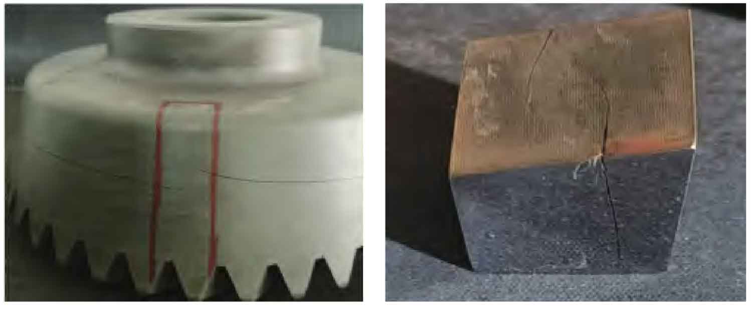
Since the crack source cannot be touched, and the hardness test of bevel gear is about 60HRC, and the sample cannot be obtained by ordinary sawing, the wire cutting is selected for sampling, which is taken from the joint at the crack tail (see Figure 1) without damaging the detection of crack source.
2. Chemical composition detection
The material of bevel gear is 18CrNiMo7-6 steel. The main elements of the sample are tested by speck spectrmax spark direct reading spectrometer. The measured analysis and smelting record composition of the sample are shown in Table 1.
| Project | C | Si | Mn | P | S | Cr | Ni | Mo | Cu |
| Sample measurement | 0.19 | 0.26 | 0.86 | 0.016 | 0.001 | 1.68 | 1.60 | 0.26 | 0.04 |
| Smelting record | 0.19 | 0.25 | 0.85 | 0.018 | 0.001 | 1.66 | 1.65 | 0.26 | 0.04 |
It can be seen from table 1 that the chemical composition of bevel gear meets the requirements of alloy structural steel (GB / T 3077-2015).
3. Residual gas and hardness test
(1) For residual gas detection, hon-2000 gas analyzer is used to detect the gas content of forgings. See Table 2 for the comparison between the analysis data of test samples and the data before delivery. It can be seen from table 2 that the display error of the final data of gas content detection is small and meets the requirements of gas detection.
| Project | [H] | [O] | [N] |
| Sampling analysis | 1.6 | 8 | 82 |
| Production record | 1.7 | 7.3 | 77 |
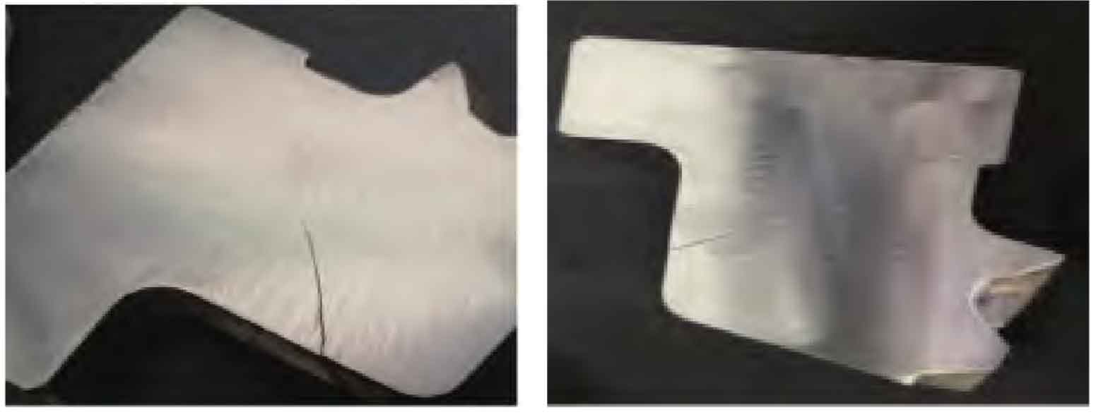
(2) Hardness test the hardness test sample is shown in Figure 2. The sample is prepared according to GB / T 230.1-2009 Rockwell hardness test of metallic materials Part 1: Test methods. The hardness test results of bevel gear, which meets the design hardness requirements.
4. Magnetic particle testing
CDX-III multipurpose magnetic particle detector shall be adopted according to J B / t5000 15-2007 general technical conditions for heavy machinery part 15: Nondestructive Testing of forged steel parts stipulates that through 360 ° magnetic particle testing on the surface of bevel gear, no relevant magnetic marks, hair lines, white spots and forging cracks are found on the near surface and surface.
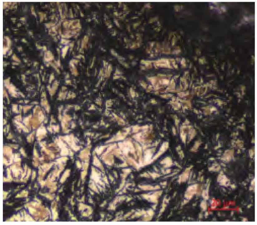
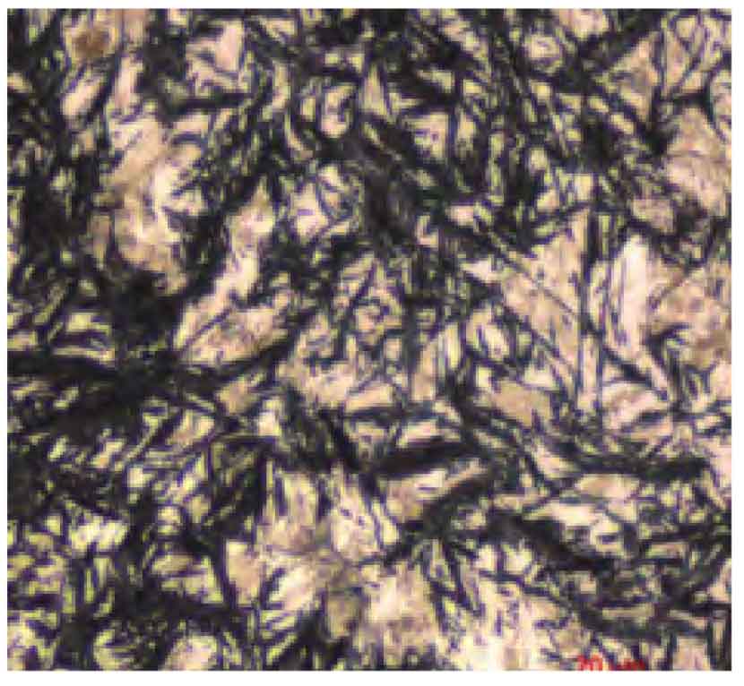
5. Metallographic structure
Use 1 0 0 × Through optical microscope observation, the evaluation of non-metallic inclusions is carried out according to GB / t10561-2005 standard rating diagram microscopic inspection method for the determination of the content of non-metallic inclusions in steel (see Fig. 3). The inclusion state is shown in Fig. 3a and B. At the same time, the sample is 100 × The microstructure was observed by optical microscope. Figure 3C shows the normal matrix structure near the crack, and figure 3D shows the measured corrosion structure in the crack area of the failure part. There is no network or abnormal carbide accumulation in the field of view.
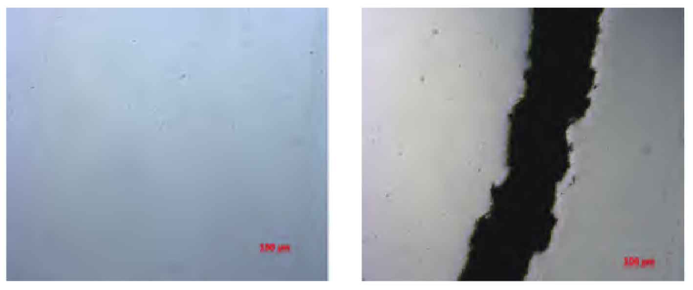
b) Inclusion state on both sides of crack
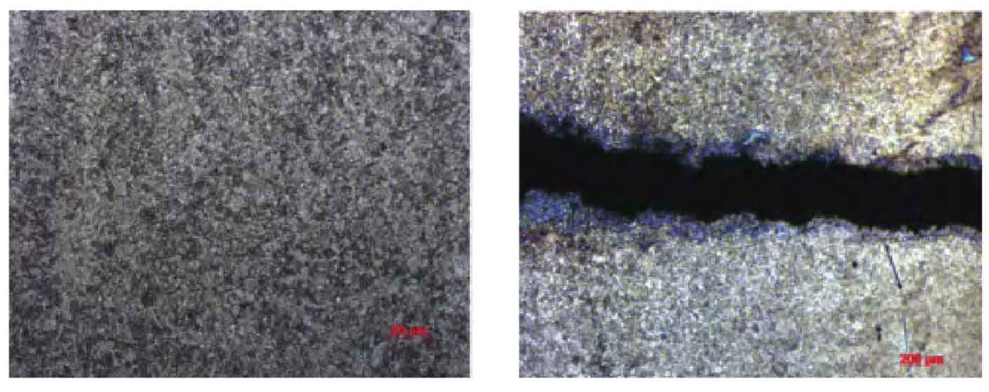
d) Microstructure on both sides of crack
6. On site inspection
Inclusions in the matrix, the detection range is full field of view, and the inclusion conditions are class a 0.5, class B 0.5, class C 0.5, class D 0.5 and DS none; As shown in Figure 4, the retained austenite on the surface of bevel gear failed parts is grade 6, and the retained austenite on the surface of furnace samples is grade 6.
According to the original records, 18 CrN I Mo 7 – 6 steel workpieces are mixed with 20CrMnTi steel workpieces, and the 20CrMnTi steel process is the main process. The detailed requirements for the implementation of the process are as follows: the carburizing and heat preservation temperature is 925 ° C. After Carburizing and quenching, the furnace cold oil drainage is required for 10m i n, and then washed by the converter and 65 ° C warm water for 45min; The tempering of converter is heated to 170 ° C according to the set rate of process and fully tempered. However, the record shows that the oil draining time is 4553s. According to the re inspection and the original record, the composition of the failed part is consistent with that of the smelting furnace number, and the beneficial elements are in the middle and upper limit; A certain amount of retained austenite and austenite on the surface of the workpiece were found to accumulate at the same time; According to the original records, the tempering will not start until the return time of tempering exceeds 2H.