
Samples are taken from the invalid gears, after grinding and polishing, the metallographic structure is observed by Olympus microscope, and metallographic analysis is carried out according to JB/T6141.3-1992 and GB/T13299-1991 standards. Rockwell hardness and microhardness meters are used to measure the hardness of gears from tooth surface to heart; JSM-6390A is used.Microstructure and failure morphology of three failed gears were observed by scanning electron microscopy (SEM) and chemical composition of three gear materials was analyzed by inductively coupled plasma emission spectrometry (ICP-AES).
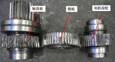
The driving mechanism of the traction part consists of three parts: motor gear, idler wheel and shaft gear. The relative positions of the three gears are shown in Figure 1.According to the failure condition and analysis needs, 1 representative sample is collected from 3 gears, and the macro failure morphology and sampling position are shown in Figure 2.
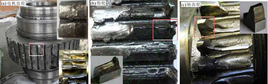
There are only 6 motor gears that have fatigue fracture on the teeth (Figure 2(a) lower right corner). The fatigue fracture is concave, only one complete fatigue fracture tooth is found, and the fatigue source is chamfer formed by the hobbing.The remaining teeth are heavily worn and the top of the teeth is completely worn off, almost flat (Figure 2(a) upper right corner), which should be wear after breaking rather than wear before breaking.The teeth of the idler wheel are crushed and deformed. Along the width of the teeth, one end of the idler wheel is heavily worn while the other end is more pronounced with fatigue wear and creases (Figure 2(b)).Looking from the width direction of the teeth of the shaft gear, there are wear marks on one end, but the wear is not too serious (Figure 2(c)), while the other end shows obvious brittle fracture, which is caused by overload fracture when the stress exceeds the ultimate strength during bending.