
Worm gear mechanisms are widely used in mechanical engineering due to their high transmission ratios, smooth operation, and low noise. However, under heavy loads and long strokes, overheating and subsequent adhesive wear can lead to sudden failure. In this study, we encountered a rare failure mode where the worm shafts experienced severe bending deformation after the worm gears seized during operation. This paper presents a comprehensive failure analysis of a worm gear lifting system, focusing on structural, material, stress, stability, and transmission aspects. Through systematic investigation, we identified root causes and proposed corrective measures. The analysis heavily relies on quantitative tables and formulas to illustrate the failure mechanisms. The term worm gears is repeatedly highlighted throughout the discussion to emphasize the core component.
The lifting mechanism consists of three SWL-25 type worm gear units arranged in a line on a third-floor platform. Each unit drives a vertical worm shaft connected to a steel lifting carriage. An electric motor located between two units provides synchronized power via half shafts and universal joints. The carriage moves along guide rails with guide wheels to control lateral sway. The system lifts a full fermentation tank from the first floor to the second floor and lowers it after the process. During operation, one side is loaded while the other is empty. Initially, the mechanism performed well, but over time all three worm shafts exhibited varying degrees of bending deformation, with worm shaft No. 2 showing the most severe curvature.
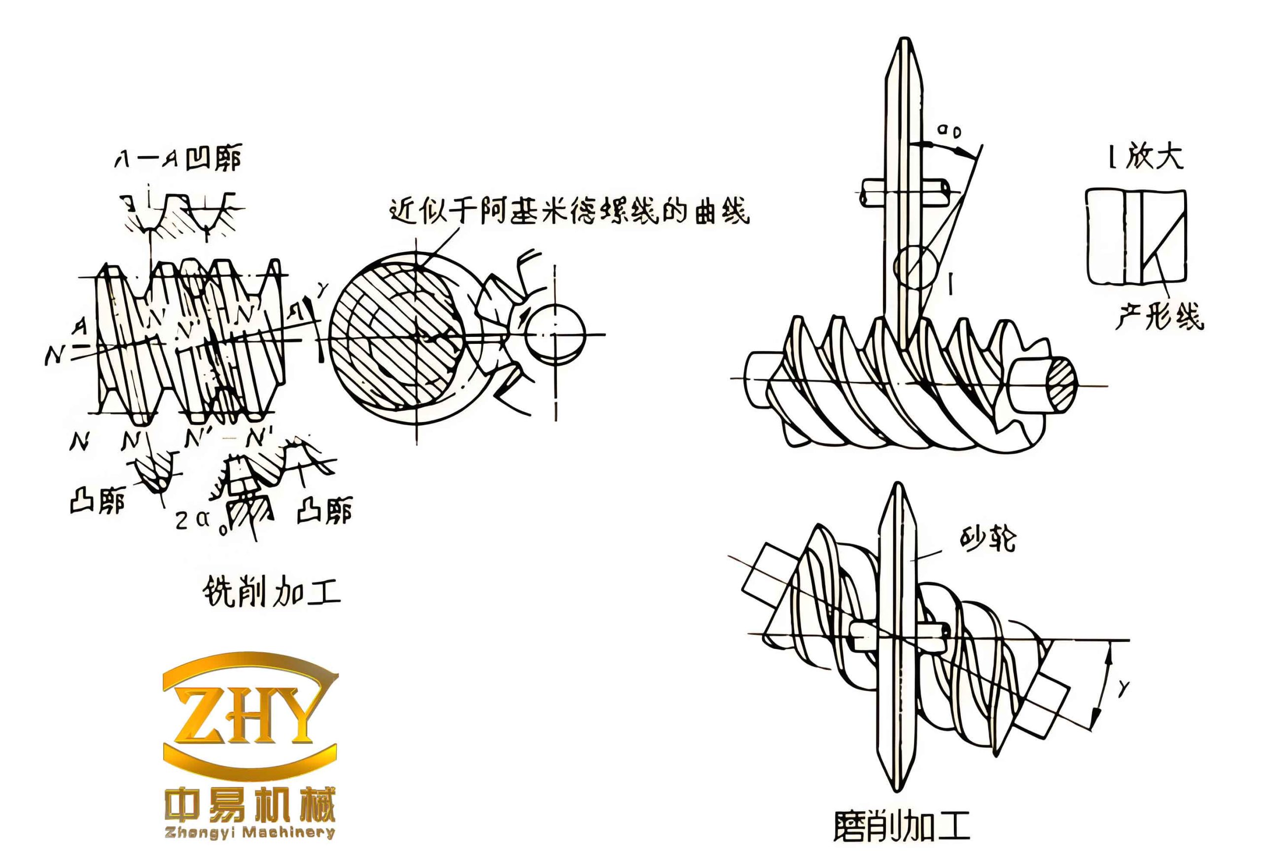
Physical Inspection and Preliminary Observations
Upon disassembly, we observed that the lubricating grease in the worm gear boxes exhibited bubbling, discoloration (darkened), and reduced volume. The worm wheel teeth showed signs of adhesive seizure. The main beam of the carriage remained undamaged, but the carriage itself was tilted relative to the guide rails. These symptoms indicated abnormal thermal conditions and possible mechanical jamming.
Material Analysis
We collected samples from the three worm shafts near their tail ends. Chemical composition was determined using spectroscopy. The results are summarized in Table 1 below.
| Element | Worm 2 – Sample 1 | Worm 2 – Sample 2 | Worm 1 – Sample | Worm 3 – Sample |
|---|---|---|---|---|
| C | 0.23% | 0.23% | 0.21% | 0.23% |
| Si | 0.21% | 0.22% | 0.21% | 0.21% |
| Mn | 0.55% | 0.55% | 0.55% | 0.54% |
| P | 0.026% | 0.028% | 0.026% | 0.026% |
| S | 0.010% | 0.011% | 0.008% | 0.009% |
| Cr | 0.037% | 0.037% | 0.039% | 0.037% |
| Ni | 0.010% | 0.011% | 0.010% | 0.009% |
| Cu | 0.022% | 0.022% | 0.022% | 0.022% |
According to the Chinese standard GB/T 699-2015 for high-quality carbon structural steels, the measured compositions correspond to grade 25 steel (0.22–0.29% C). This material has relatively low strength and hardness but good ductility. In mechanical design, shafts that transmit significant loads are conventionally made of medium-carbon quenched-and-tempered steels such as 45 steel, 40Cr, or 40CrMnTi. Using 25 steel for such an important power-transmitting component is questionable, as it increases the risk of rapid wear and galling under high sliding velocity.
Static Strength Analysis of Worm Shafts
The mechanism operates with one side loaded (full fermentation tank) while the other side is empty. We considered the worst-case scenario: lifting the loaded carriage upward. The key parameters are given below:
- Motor power: 18.5 kW, rated speed 1470 rpm
- Worm gear transmission ratio: 24:1 (actual installed)
- Worm outer diameter: 89.82 mm, root diameter d = 70 mm
- Worm length h = 5550 mm
- Distance between worms: 4900 mm
- Carriage self-weight Q₂ = 29.4 kN
- Full load weight Q₃ = 186.2 kN (applied at the center of the right side)
From the free-body diagram of the carriage, the forces F₁, F₂, F₃ on the three worms were determined using equilibrium and deformation compatibility (statically indeterminate system). The derived equations are:
$$ Q = Q_2 + Q_3 $$
$$ L = \frac{Q_2 \cdot g + 1.5 Q_3 \cdot g}{Q} $$
$$ F_1 + F_2 + F_3 = Q $$
$$ F_2 \cdot g + 2 F_3 \cdot g = Q L $$
$$ \frac{2F_2 h}{EA} = \frac{F_1 h}{EA} + \frac{F_3 h}{EA} $$
Solving these yields:
| Worm shaft | Force (kN) |
|---|---|
| F₁ (left) | 25.3 |
| F₂ (center) | 71.9 |
| F₃ (right) | 118.4 |
The maximum tensile stress in worm 3 is:
$$ \delta = \frac{F_3}{A} = \frac{4 F_3}{\pi d^2} = \frac{4 \times 118.4 \times 10^3}{\pi \times (0.07)^2} \approx 30.8 \text{ MPa} $$
The yield strength of 25 steel after heat treatment is about 275 MPa. With a safety factor of 2, the allowable stress is 137.5 MPa. Therefore, under normal steady conditions, the tensile stress is well within limits. This suggests that overloading alone did not cause the failure.
Stability Analysis of Worm Shafts
Although the static analysis shows tensile loads, the worm shafts could experience compressive forces if the worm gear seizes suddenly. During a seizure, the upper end of the worm stops rotating while the carriage continues moving upward due to inertia, placing the worm under compression. The worm is constrained as a lower-fixed, upper-pinned column. The effective length factor μ = 0.7. The slenderness ratio λ is:
$$ \lambda = \frac{\mu h}{i} = \frac{0.7 \times 5.55}{0.07/4} = 220 $$
The characteristic slenderness ratio for 25 steel is about 92.6. Since λ > 92.6, the worm is a long column and is prone to Euler buckling. The critical stress and critical load are:
$$ \delta_{cr} = \frac{\pi^2 E}{\lambda^2} = \frac{\pi^2 \times 200 \times 10^9}{220^2} \approx 40.78 \text{ MPa} $$
$$ F_{cr} = A \cdot \delta_{cr} = \frac{\pi d^2}{4} \times 40.78 \times 10^6 \approx 156.9 \text{ kN} $$
If the compressive load exceeds 156.9 kN, the worm will buckle. During seizure, the inertial dynamic factor typically ranges from 3 to 5 for lifting mechanisms. Using a factor of 3, the minimum compressive force on worm 3 would be 3 × 118.4 = 355.2 kN, far above the critical load. This explains the bending deformation observed—the worm shaft buckled under the dynamic compressive overload. The buckling shape of a fixed-pinned column matches the actual deformed profile of worm shaft No. 2, confirming this failure mode.
Transmission Ratio and Thermal Effects
Specifications for the SWL-25 worm gear unit state a recommended maximum input power of 4.8 kW per unit (total 14.4 kW), and a standard transmission ratio of 32:1 is prescribed. However, the installed units had a ratio of 24:1. This change increased the worm wheel speed from the design value of 45.9 rpm to 61.3 rpm—a 33.6% increase. Higher rotational speed dramatically elevates sliding velocity at the gear mesh, leading to increased frictional heat generation. In worm gears, the relative sliding motion produces significant heat, which degrades lubricant viscosity and can cause adhesive wear (scoring) and eventual seizure. The observed grease discoloration, bubbling, and reduced volume are direct evidence of overheating.
Table 3 compares key parameters for the two transmission ratios under full load.
| Parameter | Ratio 32:1 (design) | Ratio 24:1 (actual) | Increase (%) |
|---|---|---|---|
| Worm wheel speed (rpm) | 45.9 | 61.3 | 33.6 |
| Lifting speed (mm/s) | (based on lead) | higher | ~33.6 |
| Sliding velocity at mesh (m/s) | low | high | ~33.6 |
| Heat generation rate | moderate | significantly higher | >33.6 |
The inappropriate transmission ratio caused excessive temperature rise, which together with inadequate lubrication (grease level not maintained, wrong grease type) led to film breakdown, metal-to-metal contact, and ultimately seizure of the worm gears. Once seizure occurred, the worm shafts experienced dynamic compressive loads that exceeded the Euler buckling limit, resulting in the bending failure.
Root Causes and Recommendations
Based on our analysis, the failure of the worm gears and subsequent worm bending can be attributed to three primary factors:
- Improper transmission ratio: The substitution of a 24:1 ratio instead of the specified 32:1 increased sliding speed and heat generation, which directly caused thermal runaway and seizure of the worm gears.
- Inadequate lubrication: Failure to maintain proper grease quantity and quality (discolored, bubbled grease) exacerbated overheating and accelerated adhesive wear. The grease should have been replaced more frequently with a grade suitable for high-temperature worm gear applications.
- Unsuitable material selection: Using 25 steel (low-carbon) for the worm shafts instead of stronger medium-carbon alloys (e.g., 45 steel or 40Cr) reduced the critical buckling load and made the shaft more susceptible to bending after seizure. Although the static tensile stress was acceptable, the buckling resistance was marginal.
To prevent recurrence, we propose the following measures:
- Restore the original transmission ratio of 32:1, or add an additional reduction stage to bring the worm wheel speed within the manufacturer’s recommendation.
- Implement a strict lubrication maintenance schedule: use approved high-viscosity worm gear oil with extreme-pressure additives, and monitor temperature and grease condition regularly.
- Upgrade the worm shaft material to a medium-carbon alloy steel (e.g., 40Cr) with appropriate heat treatment to increase both static strength and buckling resistance. Alternatively, increase the shaft diameter or shorten the unsupported length to improve column stability.
- Consider installing over-speed protection or torque-limiting devices to prevent the carriage from imposing dynamic compressive loads in case of seizure.
This case demonstrates that failures in worm gear mechanisms are often multifaceted, involving not only the gear teeth themselves but also the shafts and supporting structures. A holistic approach that considers thermal, mechanical, and dynamic factors is essential for robust design and safe operation of worm gears in heavy lifting applications.