1. Introduction
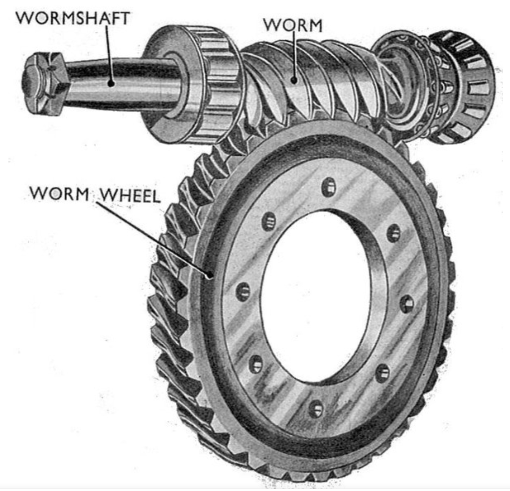
Worm gear mechanisms are widely used in heavy-load lifting systems due to their high transmission ratio, compact structure, and self-locking capability. However, unexpected failures such as bending deformation of worm screws under operational conditions remain critical challenges. This paper investigates a rare case of bending failure in a SWL-25 worm gear lifting mechanism, focusing on structural design, material properties, stress distribution, and stability analysis.
2. Structural Configuration
The lifting system employs three parallel SWL-25 worm gear units arranged linearly across a three-tiered platform. Key parameters include:
- Motor power: 18.5 kW
- Nominal speed: 1,470 rpm
- Worm screw dimensions: Ø70 mm × 5,550 mm
- Center distance between worm screws: 4,900 mm
3. Material Analysis
Chemical composition testing of failed worm screws revealed:
| Element | Worm Screw 2-1 | Worm Screw 2-2 | Worm Screw 1 | Worm Screw 3 |
|---|---|---|---|---|
| C | 0.23% | 0.23% | 0.21% | 0.23% |
| Si | 0.21% | 0.22% | 0.21% | 0.21% |
| Mn | 0.55% | 0.55% | 0.55% | 0.54% |
| P | 0.026% | 0.028% | 0.026% | 0.026% |
| S | 0.010% | 0.011% | 0.008% | 0.009% |
All specimens conformed to GB/T 699-2015 Grade 25 carbon steel specifications. However, typical worm gear applications require higher-strength materials like 45# steel or 40Cr alloys.
4. Stress Analysis
The total lifting load combines platform weight (Q₂ = 29.4 kN) and fermentation tank load (Q₃ = 186.2 kN). Force distribution equations for the three worm screws:
$$F_1 + F_2 + F_3 = Q_2 + Q_3$$
$$F_2g + 2F_3g = QL$$
$$2\frac{F_2h}{EA} = \frac{F_1h}{EA} + \frac{F_3h}{EA}$$
Solving these yields maximum tensile stress:
$$\sigma_{\text{max}} = \frac{4F_3}{\pi d^2} = 30.8\ \text{MPa}$$
Though below the yield strength (275 MPa), safety factors were compromised due to dynamic loading.
5. Stability Analysis
The worm screw’s slenderness ratio determines buckling risk. For fixed-guided constraints (\(\mu = 0.7\)):
$$\lambda = \frac{4\mu h}{d} = 220$$
Critical Euler buckling stress:
$$\sigma_{\text{cr}} = \frac{\pi^2 E}{\lambda^2} = 40.78\ \text{MPa}$$
Actual compressive stress during seizure events exceeded this threshold due to inertia forces:
$$F_{\text{cr}} = A\sigma_{\text{cr}} = 156.9\ \text{kN} < F_{\text{impact}} (355.2\ \text{kN})$$
6. Transmission Ratio Effects
Mismatched speed ratios aggravated thermal effects. For SWL-25 worm gears:
| Parameter | Design Spec | Actual |
|---|---|---|
| Speed Ratio | 32:1 | 24:1 |
| Output Speed (rpm) | 45.9 | 61.3 |
| Velocity Increase | – | 33.6% |
Increased sliding velocity at the worm gear interface raised lubrication requirements:
$$v_s = \frac{\pi d n}{60,000} \cos \gamma$$
Where \(\gamma\) = lead angle, \(d\) = pitch diameter, \(n\) = rpm. Higher \(v_s\) accelerated lubricant degradation.
7. Lubrication Failure
Thermal analysis of worm gear contact shows temperature rise proportional to friction power loss:
$$\Delta T = \frac{\mu W v_s}{J A}$$
Where \(\mu\) = friction coefficient, \(W\) = load, \(J\) = mechanical equivalent, \(A\) = heat dissipation area. Inadequate lubrication increased \(\mu\) from 0.02–0.08 (typical) to >0.15, causing thermal seizure.
8. Design Recommendations
- Implement speed ratio verification: $$i_{\text{required}} \geq \sqrt{\frac{\pi^2 E I}{4 P_{\text{cr}} h^2}}$$
- Upgrade material to 40Cr with tempered hardness HRC 28–32
- Install temperature sensors with threshold ≤90°C
- Use synthetic lubricant with EP additives (viscosity ≥680 cSt @40°C)
9. Conclusion
This failure analysis demonstrates that worm gear lifting mechanisms require integrated consideration of transmission ratios, stability limits, and thermal management. Proper speed ratio selection combined with enhanced lubrication practices can prevent bending failures while maintaining lifting efficiency. Future designs should incorporate real-time monitoring systems for critical parameters affecting worm gear performance.
