Bending fracture of teeth and pitting and flaking of tooth surface are the two most common failure modes of main bevel gears of axles. Therefore, checking of bending strength and contact strength is established respectively for these two failure modes. In practical application, we are more concerned about the service life of gear pairs. Therefore, not only contact stress and bending stress but also cycle number of gear pairs should be considered in strength checking.Number.
At present, the fatigue bearing capacity of hypoid gear pair mainly uses the checking method given by Grison Company. This method has been modified and optimized for several decades, and it has high safety and reliability.
1. Bending fatigue strength
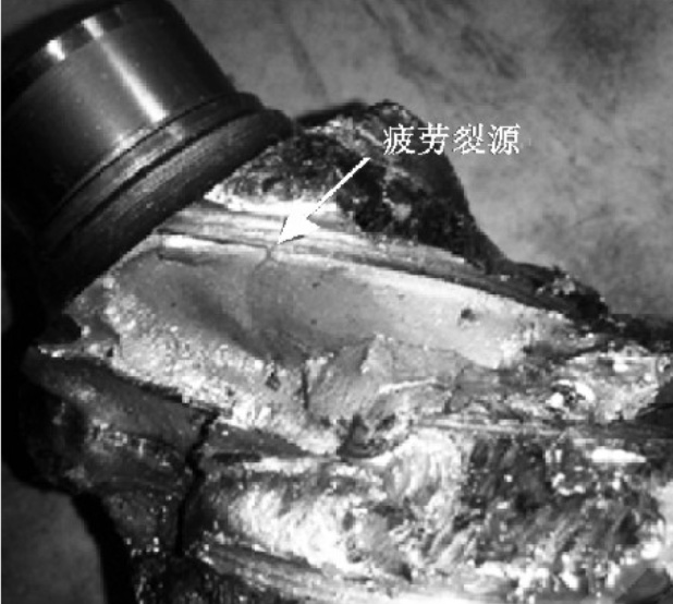
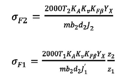
A common bending fatigue case of hypoid gear roots in the aftermarket is shown in Figure 1. The fatigue source is mostly located at a slightly smaller end in the middle of the small tooth width.Formulas for calculating bending fatigue stress of hypoid gear roots are given in this paper.

Where: T1/T2 is small/large wheel torque (Nm), KA is service factor, Kv is dynamic load coefficient, KFbeta is tooth load distribution coefficient, YX is bending dimension coefficient, m is large end module, B2 is large tooth width, D2 is large wheel pitch circle diameter, J1/J2 is small/large wheel bending geometry coefficient, z1/z2 is small/large wheel teeth number.

2. Contact fatigue strength
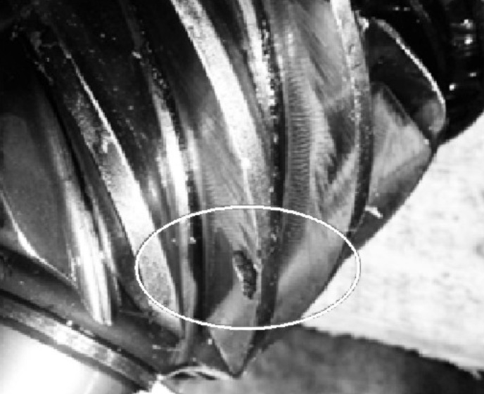
A case of contact fatigue failure of helical bevel gears at the initial stage of failure is shown in Figure 2. Flake flaking occurs over time, which ultimately results in tooth cutting of the entire gear teeth.The tooth contact stress formula is shown in the formula.

Where ZE is the elastic coefficient, T1max is the maximum torque of the small wheel, KHbeta is the load distribution coefficient in the tooth direction, ZX is the contact dimension coefficient and ZR is the surface condition coefficient.

3. Macro-parameter optimization of wheel blank
The design of hypoid gear pair includes macro-blank design and micro-modification design.Macro-blank design is the foundation and plays a leading role.
According to equation (1) – (3), the optimum direction of macro-parameters can be determined. The influence parameters of root bending stress are m, B2 and d2. The larger the three parameters, the smaller the root bending stress and the stronger the bearing capacity.The main influencing parameters of tooth surface contact stress are B2 and d2. The larger the two parameters, the smaller the contact stress.Therefore, if there is enough space, the modulus, tooth width and pitch circle diameter should be enlarged to reduce the bending stress of the root and contact stress of the tooth surface.
Gear pair geometric coefficients I and J take into account factors such as tooth profile coefficient, position of load action point, load distribution between teeth, effective tooth width, stress concentration and overlap, etc. They can be increased by optimizing parameters such as high tooth coefficient and tooth thickness, thus improving the gear bearing capacity.
