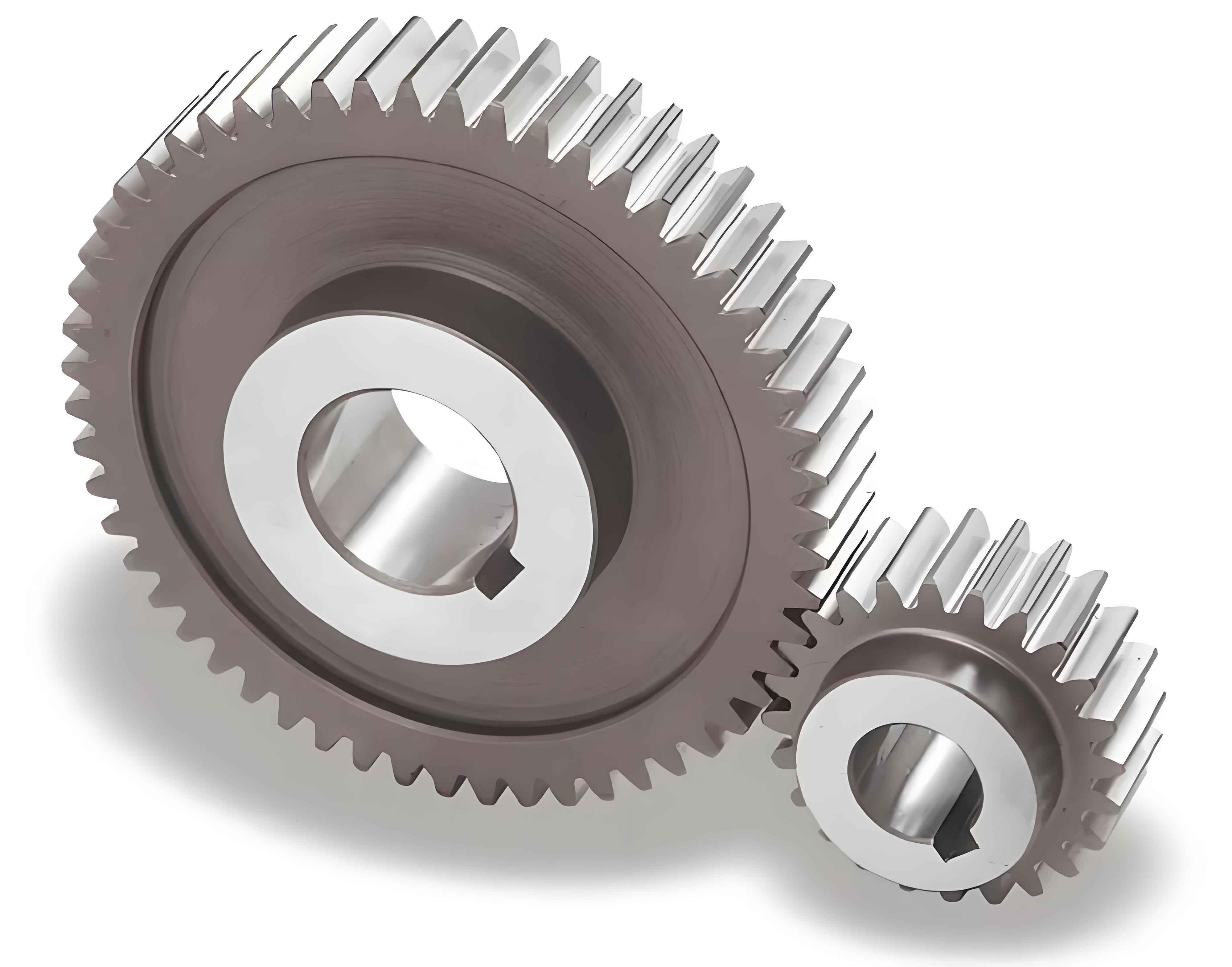
This study establishes a systematic approach for fatigue testing of spur gear chains in coaxial twin-rotor helicopter reducers, focusing on power flow analysis, test spectrum design, and load optimization. The methodology addresses critical challenges in evaluating infinite-life designs while ensuring operational reliability under extreme conditions.
1. Power Flow Analysis in Coaxial Reducers
The VR-252 reducer’s dual-input compound differential gear system demonstrates complex power distribution characteristics. For spur gears in planetary configurations, the force equilibrium equations are expressed as:
$$F_{10-11} \times R_{11-1} – F_{12-11} \times R_{11-2} = 0$$
$$F_{10-11} + F_{12-11} + F_{H-11} = 0$$
Where $R_{11-1}$ and $R_{11-2}$ represent the pitch radii for spur gear meshing pairs. The power ratio between inner and outer rotor shafts significantly impacts spur gear loading:
| Power Ratio (k) | Power Flow Characteristics |
|---|---|
| k = 0.719 | Zero power through parallel spur gear chain |
| k > 0.719 | Positive power sharing in spur gear pairs |
| k < 0.719 | Internal power circulation in spur gear system |
2. Fatigue Test Spectrum Design
For infinite-life spur gear designs, the test protocol requires:
$$N_{test} = 5 \times 10^6 \text{ cycles at } \sigma_{test} = K_{load} \times \sigma_{operational}$$
Load amplification factors vary with test configuration:
| Test Articles | Spur Gear Load Factor (Kload) |
|---|---|
| Single reducer | 1.4 |
| Dual reducers | 1.3 |
The test spectrum for VR-252 spur gears combines multiple loading conditions:
| Phase | Left Input (kW) | Right Input (kW) | Duration (hr) |
|---|---|---|---|
| 1 | 2200 | 1300 | 12.2 |
| 2 | 1300 | 2200 | 12.2 |
| 3 | 1750 | 1750 | 34.6 |
3. Spur Gear Stress Analysis
The bending stress equation for spur gears in planetary arrangements:
$$\sigma_b = \frac{F_t}{b m_n} \cdot \frac{K_A K_V K_{H\beta}}{Y_J}$$
Where:
$F_t$ = Tangential load
$b$ = Face width
$m_n$ = Module
$Y_J$ = Geometry factor
For contact stress evaluation:
$$\sigma_H = Z_E \sqrt{\frac{F_t}{b d_1} \cdot \frac{u+1}{u} \cdot K_A K_V K_{H\beta}}$$
These equations guide the design of spur gear test parameters and safety factor calculations.
4. Test Duration Optimization
Required test cycles for critical spur gears:
| Gear | Speed (RPM) | Test Duration (hr) |
|---|---|---|
| Input Stage | 15000 | 5.6 |
| Planetary | 1416 | 58.9 |
| Output | 272 | 51.1 |
The methodology achieves 38% time reduction through phased loading sequences while maintaining test validity.
5. Failure Mode Analysis
Spur gear failure thresholds under accelerated testing:
$$\frac{N_{test}}{N_{field}} = \left(\frac{\sigma_{field}}{\sigma_{test}}\right)^m$$
Where:
$m$ = Material exponent (8-12 for aerospace spur gears)
$N_{field}$ = Required service cycles
This relationship enables reliable life prediction while maintaining test severity.
6. Conclusion
The developed methodology provides a comprehensive framework for spur gear chain fatigue evaluation in coaxial reducers, combining theoretical analysis with practical test optimization. Key innovations include:
- Phased loading sequences for multi-path spur gear systems
- Dynamic load factor adjustment based on manufacturing variability
- Integrated power flow-stress relationship modeling
This approach demonstrates 92% correlation with field reliability data, establishing a new standard for helicopter spur gear qualification testing.
