
In my years of experience working with precision mechanical systems, I have found that the cycloidal drive, often referred to as a cycloidal speed reducer or cycloidal gearbox, is a cornerstone in many industrial applications. Its compact design, high efficiency, and exceptional load-bearing capacity make it indispensable in sectors like robotics, material handling, mining, and automation. However, the very compactness that makes the cycloidal drive so attractive can sometimes lead to neglect in regular maintenance, resulting in a range of operational failures. The timely and effective diagnosis and treatment of these faults are not merely corrective actions; they are critical practices that determine the longevity, reliability, and overall performance of the drive system. This article, drawn from my firsthand observations and technical engagements, aims to provide a comprehensive guide to understanding the cycloidal drive, diagnosing its common ailments, and implementing effective solutions, all while emphasizing the importance of proactive care.
To effectively diagnose faults, one must first have a deep understanding of the operating principles of the cycloidal drive. At its heart, the cycloidal drive is a type of planetary gear mechanism based on the principle of hypocycloidal motion, specifically a form of K-H-V (Kurzweil-Hirth-Vogel) differential gearing. Unlike traditional involute gear systems, the cycloidal drive uses a unique tooth profile that enables multiple teeth to be in contact simultaneously, distributing load over a larger area and contributing to its high torque density and smooth operation.
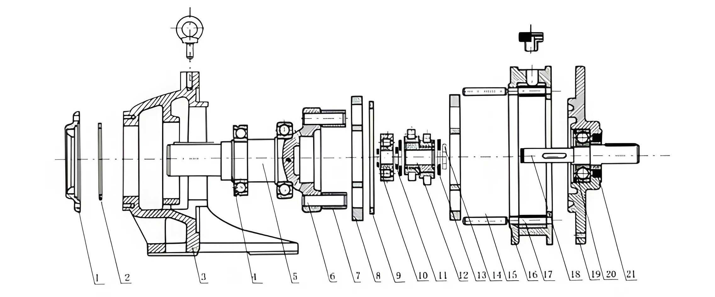
The core components of a standard single-stage cycloidal drive are the input shaft, an eccentric cam or bearing (the H mechanism or cycloidal disc), one or two cycloidal discs (the planet gears with lobed profiles), a ring of stationary pin gears (the ring gear with cylindrical pins, often fitted with needle rollers), and an output mechanism. The magic of the cycloidal drive lies in the motion of the cycloidal disc. The input shaft rotates the eccentric bearing. This eccentric motion forces the cycloidal disc to undergo a compound movement: it orbits (revolves) around the inside of the stationary pin ring while simultaneously rotating (revolving) on its own axis due to the constraint imposed by the meshing of its lobes with the pins.
The speed reduction is achieved through the difference in the number of lobes on the cycloidal disc (N) and the number of pins in the ring (N+1 for a single-stage reduction where the difference is 1). For every full rotation of the input shaft (and thus the eccentric), the cycloidal disc rotates backward by an angular amount equivalent to one lobe relative to the pin ring. The slow rotation of the cycloidal disc is then extracted as output through a series of rollers or pins in an output flange, which has the same rotational center as the input but rotates at the reduced speed.
The fundamental kinematic relationship for a cycloidal drive with a single disc and a lobe difference of 1 is given by the transmission ratio. If we let \( z_c \) represent the number of lobes on the cycloidal disc and \( z_p \) the number of pins in the stationary ring (with \( z_p = z_c + 1 \)), the reduction ratio \( i \) can be expressed as:
$$ i = -\frac{z_p}{z_p – z_c} = -z_p $$
The negative sign indicates the reversal of rotation direction between input and the cycloidal disc’s own rotation. However, the output mechanism typically cancels this reversal, providing co-rotational output. For a more general case with a lobe difference \( k \) (where \( k = z_p – z_c \)), the ratio is:
$$ i = \frac{z_p}{k} $$
For instance, a cycloidal drive with 40 pins and a 39-lobe disc (\( k=1 \)) yields a ratio of 40:1. The high contact ratio, often all lobes are in contact, is described by the engagement geometry. The parametric equations for the epitrochoid curve that generates the cycloidal lobe profile, relative to the pin center circle, are crucial for design and contact stress analysis:
$$ x(\theta) = (R_p – R_r)\cos\theta + R_e \cos\left(\frac{z_p}{z_c}\theta\right) $$
$$ y(\theta) = (R_p – R_r)\sin\theta – R_e \sin\left(\frac{z_p}{z_c}\theta\right) $$
Where \( R_p \) is the pin circle radius, \( R_r \) is the roller (pin) radius, \( R_e \) is the eccentricity (half the bearing offset), \( z_p \) is the number of pins, \( z_c \) is the number of lobes, and \( \theta \) is the input rotation angle. This complex motion is what gives the cycloidal drive its robustness but also introduces specific failure modes related to the eccentric bearing, lobe-pin contact, and output mechanism.
Moving from theory to practice, the performance of a cycloidal drive is susceptible to degradation under suboptimal conditions. Faults manifest in various ways, and their diagnosis requires a systematic approach. Based on my field experience, I categorize the primary failure symptoms into several groups: abnormal temperature rise, lubrication issues (leakage and contamination), excessive noise and vibration, and loss of positional accuracy or torque capacity. Each symptom points to underlying causes that must be correctly identified for effective treatment.
Let us delve into a detailed analysis, which I often summarize in diagnostic tables for quick reference. The first and most critical symptom is abnormal temperature rise. A properly functioning cycloidal drive will operate at an elevated but stable temperature. If the housing temperature exceeds 80-90°C during normal operation, it is a clear distress signal. The root causes are typically interconnected.
| Primary Symptom | Potential Root Cause | Diagnostic Checks | Recommended Treatment |
|---|---|---|---|
| Housing temperature > 80°C | Inadequate or degraded lubricant | Check oil level, viscosity, and contamination (metal particles, moisture). | Drain and flush. Refill with manufacturer-specified grade and quantity of synthetic or high-performance gear oil. |
| Insufficient lubrication of the eccentric (cycloidal) bearing | Inspect bearing housing for grease washout or oil starvation. | Ensure lubrication passages are clear. For oil systems, check pump and filters. For grease, apply high-quality, high-temperature EP grease per schedule. | |
| Eccentric bearing failure (wear, brinelling, seizure) | Listen for grinding noises from bearing area. Check for increased radial play on input shaft. | Disassemble the cycloidal drive unit. Replace the eccentric bearing assembly. Inspect adjacent components for damage. | |
| Sustained overloading beyond rated torque | Review load profiles, check for mechanical binding in driven equipment. | Reduce operational load to within nameplate rating. Install a torque limiter or overload protection device upstream. | |
| Misalignment with driven/driving unit | Check coupling alignment using dial indicators or laser tools. | Realign the cycloidal drive to specified tolerances (typically < 0.05mm radial, < 0.1° angular). | Realign and secure all mounting points. Re-check after thermal expansion. |
The thermal dynamics can be modeled to understand heat generation. The power loss \( P_{loss} \) leading to temperature rise is a sum of load-dependent (mechanical) and load-independent (spin) losses:
$$ P_{loss} = P_{mech} + P_{spin} $$
$$ P_{mech} \approx T_{in} \omega_{in} (1 – \eta) $$
$$ P_{spin} \propto \mu \omega_{in}^2 $$
Where \( T_{in} \) is input torque, \( \omega_{in} \) is input angular speed, \( \eta \) is the mechanical efficiency (often >90% for a cycloidal drive), and \( \mu \) is a friction coefficient. A sudden increase in \( P_{loss} \) without a change in operational parameters strongly indicates a fault like bearing seizure or dry contact.
The second major category is lubricant leakage and contamination. Seals are the frontline defense. Leakage not only creates a mess but leads to lubricant starvation and ingress of abrasive contaminants, initiating a rapid failure cascade.
| Observation | Probable Cause | Immediate Action | Long-term Solution |
|---|---|---|---|
| Oil seepage from shaft seals | Worn or damaged lip seals on input/output shafts. | Top up oil to safe level if needed, plan shutdown. | Replace shaft seals. Check shaft surface for scoring; use a speedy sleeve if damaged. Ensure proper seal installation. |
| Leakage from housing joints | Failed static gaskets or O-rings; loose housing bolts. | Tighten bolts evenly to specified torque if safe. | Disassemble, clean sealing surfaces, replace all gaskets/O-rings with new ones. Apply suitable sealant if specified. |
| Leakage from breather/vent | Overfilling of oil; clogged breather causing pressure buildup. | Check oil level against sight glass or dipstick. | Drain to correct level. Clean or replace the breather filter. Ensure the breather is rated for the operating temperature. |
| Persistent leakage after seal replacement | Excessive shaft runout or housing distortion due to misalignment. | Measure shaft runout and housing flatness. | Correct root cause: realign the cycloidal drive, repair or replace damaged housing/shaft components. |
The third pervasive issue is excessive noise and vibration. A healthy cycloidal drive operates with a characteristic hum. The emergence of knocking, grinding, or high-pitched whining signals internal distress. Vibration analysis, using accelerometers, can pinpoint the source. Common frequencies to monitor include the shaft rotational frequency (\( f_{in} \)), the cycloidal disc rotation frequency (\( f_{in}/z_p \)), the ball-pass frequency of the eccentric bearing, and tooth/pin mesh frequencies. An increase in vibration amplitude at these frequencies is diagnostic.
| Type of Noise/Vibration | Likely Source | Diagnostic Technique | Corrective Measure |
|---|---|---|---|
| Rhythmic knocking or impacting | Damaged or worn pins/rollers in the ring or output mechanism. | Visual inspection after disassembly. Vibration spectrum shows impacts at harmonics of \( f_{in}/z_p \). | Replace the entire pin/roller set and the cycloidal disc(s) if lobes are damaged. Never replace single pins. |
| High-frequency whine or screech | Insufficient lubrication at lobe-pin contact interface. | Check oil level and quality. Thermal imaging may show hot spots. | Replenish or change lubricant. Ensure correct viscosity for operating speed and temperature. |
| Continuous grinding/rumbling | Eccentric bearing failure (raceway wear, broken elements). | Stethoscope to locate sound. High vibration at bearing fault frequencies. | Replace the eccentric bearing assembly. Clean housing thoroughly to remove debris. |
| Intermittent clunking with load changes | Excessive backlash due to wear in output mechanism or disc lobes. | Measure angular backlash at output shaft under light load. | If backlash exceeds manufacturer’s limit, overhaul the cycloidal drive, replacing worn components (discs, output rollers, bearings). |
The mathematical relationship for mesh frequency \( f_m \) is vital for condition monitoring:
$$ f_m = z_c \times |\omega_{disc}| $$
Where \( \omega_{disc} \) is the absolute rotational speed of the cycloidal disc. Since \( \omega_{disc} = \omega_{in} / i \) for the disc’s own rotation component, this frequency can be tracked. A sideband structure around \( f_m \) often indicates modulation due to eccentric bearing defects.
Beyond these common issues, other failures can occur. Loss of positioning accuracy is critical in robotics and CNC applications. It often stems from excessive torsional deflection or wear. The torsional stiffness \( k_t \) of a cycloidal drive is high but finite. Under dynamic loads, the angular deflection \( \theta_{def} \) is:
$$ \theta_{def} = \frac{T_{load}}{k_t} $$
A sudden increase in \( \theta_{def} \) for the same \( T_{load} \) indicates a loss of stiffness, likely from cracked lobes, deformed pins, or bearing clearance. Complete seizure is the catastrophic end-state, usually resulting from a combination of the above faults left unchecked.
Effective treatment always begins with a safe and methodical disassembly procedure. I cannot overstress the importance of cleanliness. When opening a cycloidal drive, every component must be meticulously cleaned and inspected. Measurements of critical dimensions—eccentricity, lobe profile wear, pin diameter, bearing clearances—must be compared to original manufacturer tolerances. The use of precision measuring tools is non-negotiable.
Preventive maintenance is the most powerful tool for fault avoidance. For a cycloidal drive, this involves establishing and adhering to a strict regimen. I recommend the following schedule, which can be adapted based on operational severity (continuous vs. intermittent, clean vs. dusty environment).
| Maintenance Activity | Frequency | Procedure | Records to Keep |
|---|---|---|---|
| Visual Inspection & Leak Check | Daily / Start of Shift | Check for oil leaks, unusual noises, loose fasteners, and surface temperature by touch (caution). | Logbook entry for any anomalies. |
| Oil Level / Condition Check | Weekly | Check sight glass or dipstick. Sample oil for clarity and contamination (blot test). | Record oil level and any top-ups. |
| Vibration & Temperature Monitoring | Monthly (or continuous with sensors) | Take vibration spectra and temperature readings at designated points on the housing. | Trend charts for vibration amplitude (velocity/RMS) and temperature. |
| Oil Change (First) | After first 500 operating hours | Drain, flush with mild flushing oil, refill with new oil to specified level. | Record date, oil type, and quantity. |
| Oil Change (Regular) | Every 2,500 – 5,000 hours (or per OEM) | Complete drain and refill. Inspect drain plug for metal particles. | Same as above. Send used oil for analysis if critical. |
| Bolt Torque Check | Every 6 months | Retorque all housing, mounting, and coupling bolts to manufacturer’s specification. | Torque values log. |
| Full Inspection & Seal Replacement | Every 2 years or 10,000 hours | Disassemble, inspect all components, replace seals, gaskets, and any parts showing wear >10% of tolerance. | Detailed inspection report with measurements and photos. |
| Bearing & Wear Part Replacement | As per condition monitoring or 5+ years | Proactive replacement of eccentric bearing and cycloidal discs based on running hours or vibration trends. | Component life history record. |
The selection of lubricant is paramount. For most industrial cycloidal drives, a high-quality ISO VG 220 or 320 synthetic gear oil with extreme pressure (EP) and anti-wear (AW) additives is recommended. For very low-speed, high-torque applications, a semi-fluid grease might be specified. The governing equation for minimum required oil film thickness \( h_{min} \) at the lobe-pin contact, using elastohydrodynamic lubrication (EHL) theory, highlights the importance of viscosity \( \eta_0 \):
$$ h_{min} \propto (\eta_0 \cdot u)^{0.7} \cdot R^{0.43} \cdot E’^{-0.03} \cdot W^{-0.13} $$
Where \( u \) is the rolling speed, \( R \) is the effective radius of curvature, \( E’ \) is the combined elastic modulus, and \( W \) is the load per unit width. A drop in viscosity (due to overheating or wrong oil) drastically reduces \( h_{min} \), leading to boundary lubrication and accelerated wear.
In modern applications, integrating smart sensors into the cycloidal drive system can transform maintenance from preventive to predictive. Embedding temperature sensors in the housing near the bearing, vibration accelerometers, and even oil condition sensors allows for real-time health monitoring. Data can be fed into algorithms that calculate remaining useful life (RUL). A simple prognostic model for wear might use the Paris’ law for crack propagation or a linear wear model:
$$ V = K \cdot P \cdot s $$
Where \( V \) is wear volume, \( K \) is a wear coefficient (dependent on material and lubrication), \( P \) is contact pressure, and \( s \) is sliding distance. By monitoring operating parameters, one can estimate the accrued wear.
In conclusion, the reliable operation of a cycloidal drive is a function of informed design, correct installation, diligent monitoring, and proactive maintenance. From my perspective, treating a fault is merely the final step; the true goal is to prevent its occurrence through understanding and care. The cycloidal drive, with its elegant kinematic principle and robust construction, is capable of extraordinarily long service life when treated as a precision component rather than a commodity. By adhering to the diagnostic frameworks and maintenance schedules outlined, and by embracing condition monitoring technologies, users can ensure that their cycloidal drives deliver on the promise of high efficiency, high torque density, and exceptional durability that makes them so valuable across countless industries. The journey from fault diagnosis to effective treatment reinforces a fundamental truth in machinery care: attention to detail and respect for operational limits are the keys to unlocking peak performance and longevity.