
In modern mechanical transmission systems, spiral bevel gears are widely used in high-speed, heavy-load, and smooth transmission applications due to their superior performance. The trend in manufacturing technology for spiral bevel gears is shifting toward near-net shape forming processes, with precision forging being a representative method. This approach offers advantages in terms of efficiency, strength, cost reduction, energy consumption, and environmental friendliness. However, a critical issue in the precision forging of spiral bevel gears is the feasibility of demolding the forged workpiece from the die. If not properly addressed during the design phase, demolding failures can occur, leading to gear tooth damage due to interference during motion. This study focuses on investigating the demolding feasibility of spiral bevel gear forgings using dynamic simulation software, specifically ADAMS. I will explore the methodology, parameter settings, and analysis results to determine whether a spiral bevel gear can be successfully demolded after forging, with an emphasis on the influence of spiral angle and cone angle parameters.
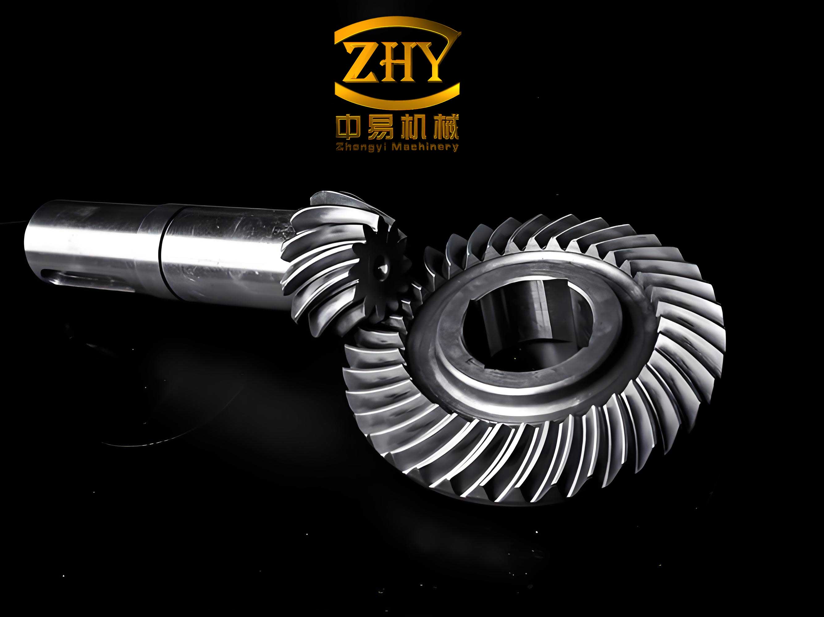
The complexity of spiral bevel gears lies in their intricate spatial curved surfaces, which pose challenges in forging and demolding processes. For instance, a spiral bevel gear with zero spiral angle may be impossible to demold without causing interference, whereas a gear with a non-zero spiral angle (e.g., 35°) might allow successful demolding. This highlights the importance of conducting a demolding feasibility analysis before die design. In this research, I utilize three-dimensional engineering software for die design and integrate it with ADAMS to perform dynamic simulations of the demolding process. The goal is to develop a systematic approach for assessing demolding feasibility based on force analysis during spiral motion.
To achieve this, I first create a parametric three-dimensional model of the spiral bevel gear in a CAD environment, such as Pro/ENGINEER. The modeling process involves defining key parameters like spiral angle, cone angle, module, and number of teeth. For a spiral bevel gear, the tooth geometry can be described using mathematical equations. The spiral bevel gear tooth surface is typically generated based on gear theory, and the parametric model allows for easy modification of design parameters. Once the model is ready, I use software interfaces (e.g., the Mechanism/Pro module in Pro/E) to export it to ADAMS, ensuring unit consistency to avoid errors. In ADAMS, the gear is treated as a rigid body with defined material properties, such as steel, and mass attributes. The die, particularly the concave die (female die), is created using Boolean operations in the CAD software or directly in ADAMS to represent the forging cavity. This integrated workflow enables seamless transition from design to simulation.
The core idea of the demolding feasibility study revolves around simulating the spiral motion of the forged spiral bevel gear as it exits the die. In ADAMS, I define a “general point motion” drive to achieve this spiral motion, which combines linear displacement along the axial direction and rotational displacement around the axis. The motion is based on a helical path derived from the gear’s geometry. Specifically, I extract a helical curve from the gear, such as the root cone helix, and discretize it into steps. For each step, the axial displacement (Δz) and corresponding angular rotation (Δθ) are calculated. These values are then used to define the motion in ADAMS as a function of time. For example, if the axial velocity is constant at v = 10 mm/s, the angular velocity ω at each time step can be determined from the ratio Δθ/Δz. This approach effectively models the demolding process as a variable-lead screw motion.
The mathematical representation of the helical curve for a spiral bevel gear can be expressed using parametric equations. For a point on the root cone helix, the coordinates in a cylindrical system are given by:
$$ r = R_{root} – \frac{z \tan(\alpha)}{L} $$
$$ \theta = \frac{2\pi z}{P} + \theta_0 $$
where \( r \) is the radial distance, \( R_{root} \) is the root cone radius, \( z \) is the axial coordinate, \( \alpha \) is the cone angle, \( L \) is the length of the gear, \( \theta \) is the angular position, \( P \) is the lead of the helix, and \( \theta_0 \) is the initial angle. The spiral angle \( \beta \) is related to the lead by:
$$ \tan(\beta) = \frac{r \cdot d\theta}{dz} $$
For a spiral bevel gear, the spiral angle varies along the tooth length, but for simplicity in simulation, an average value can be used. In ADAMS, I input these parameters to define the motion drive. The table below summarizes key parameters for two spiral bevel gears with different spiral angles used in this study:
| Parameter | Gear A (Spiral Angle 0°) | Gear B (Spiral Angle 35°) |
|---|---|---|
| Number of Teeth (z) | 20 | 20 |
| Module (m) [mm] | 5 | 5 |
| Cone Angle (α) [°] | 30 | 30 |
| Spiral Angle (β) [°] | 0 | 35 |
| Root Cone Radius (R_root) [mm] | 50 | 50 |
| Axial Velocity (v) [mm/s] | 10 | 10 |
During demolding, contact forces between the spiral bevel gear forging and the die are critical. ADAMS computes these forces using a penalty-based contact algorithm. The normal contact force \( F_n \) is modeled as a function of penetration depth \( \delta \) and relative velocity. The equation for the normal force is:
$$ F_n = k \cdot \delta^e + c \cdot \dot{\delta} $$
where \( k \) is the stiffness coefficient, \( \delta \) is the penetration depth, \( e \) is the nonlinear force exponent, \( c \) is the damping coefficient, and \( \dot{\delta} \) is the relative normal velocity. For steel-on-steel contact, typical values are \( k = 1.0 \times 10^5 \, \text{N/mm} \), \( e = 1.5 \), and \( c \) is set to 0.1% of \( k \) to avoid discontinuities. The damping force helps stabilize the simulation by dissipating energy. Proper setting of these parameters is essential for accurate results. In this study, I use a penetration depth of \( \delta = 0.001 \, \text{mm} \) to minimize numerical errors. The contact force model allows me to analyze the forces exerted on the gear teeth during demolding, which directly indicates the risk of damage.
For the motion analysis, I simulate the demolding process for spiral bevel gears with different spiral angles. Using ADAMS, I apply the spiral motion drive to the gear and monitor the contact forces on the tooth surfaces over time. The simulation time is set to 1 second, with a step size of 0.01 seconds. The results are processed using ADAMS/PostProcessor to plot force versus time curves. For Gear A (0° spiral angle), the contact forces spike to over 500 N within 0.15 seconds, indicating severe interference that would likely destroy the teeth. In contrast, for Gear B (35° spiral angle), the maximum contact force is only about 15 N during the same period, with a smooth demolding process as the gear moves axially by 10 mm. This suggests that demolding is feasible for spiral bevel gears with sufficient spiral angles.
To further quantify the demolding feasibility, I define a demolding force threshold \( F_{threshold} \) as the maximum allowable force before tooth damage occurs. Based on material properties, for a typical forged steel spiral bevel gear, \( F_{threshold} \) can be estimated using the yield strength \( \sigma_y \) and tooth cross-sectional area \( A \):
$$ F_{threshold} = \sigma_y \cdot A $$
For steel with \( \sigma_y = 600 \, \text{MPa} \) and a tooth area of approximately 10 mm², \( F_{threshold} \approx 6000 \, \text{N} \). In the simulation, if the contact force exceeds this value, demolding is considered infeasible. The table below summarizes the simulation results for various spiral angles, keeping other parameters constant:
| Spiral Angle β [°] | Max Contact Force [N] | Demolding Feasibility | Axial Displacement at Demolding [mm] |
|---|---|---|---|
| 0 | >500 | No | N/A |
| 15 | 250 | Yes | 8 |
| 25 | 100 | Yes | 6 |
| 35 | 15 | Yes | 5 |
| 45 | 5 | Yes | 4 |
The data shows that as the spiral angle increases, the maximum contact force decreases significantly, making demolding easier. This is because a higher spiral angle introduces a helical path that reduces interference between the gear teeth and the die. The relationship between spiral angle and demolding force can be approximated by an exponential decay function:
$$ F_{max} = F_0 \cdot e^{-\lambda \beta} $$
where \( F_0 \) is the force at zero spiral angle, and \( \lambda \) is a decay constant determined by gear geometry. For the gears in this study, fitting the data yields \( \lambda \approx 0.05 \, \text{per degree} \). This formula can be used in the design phase to estimate demolding forces for spiral bevel gears with different spiral angles.
In addition to spiral angle, other factors influence demolding feasibility, such as cone angle, tooth profile, and lubrication. I conduct further simulations to explore these effects. For instance, varying the cone angle from 20° to 40° while keeping the spiral angle at 35°, the contact forces change due to altered tooth engagement. The results indicate that smaller cone angles generally lead to lower demolding forces, as the teeth are less steep. However, this must be balanced with functional requirements. The tooth profile, defined by pressure angle and fillet radius, also affects forces. A larger fillet radius reduces stress concentrations, lowering contact forces during demolding. These insights highlight the need for a holistic design approach for spiral bevel gear forgings.
The integration of CAD and ADAMS enables efficient iteration of design parameters. I use parametric modeling to quickly generate spiral bevel gear variants and simulate their demolding processes. This workflow reduces the need for physical prototyping, saving time and costs. Moreover, the dynamic simulation provides visual feedback on the demolding motion, allowing me to identify potential interference points. For example, in some cases, the gear may tilt during demolding, causing asymmetric forces. ADAMS can capture such phenomena by including flexibility or multi-body dynamics, though in this study, I assume rigid bodies for simplicity.
Based on the simulation results, I develop guidelines for designing spiral bevel gear forging dies. First, the spiral angle should be sufficient to ensure demolding feasibility—typically above 15° for common gear sizes. Second, the demolding motion should follow the root cone helix, as it minimizes contact forces compared to the pitch or face cones. Third, the die taper (draft angle) can be optimized to further reduce forces. The optimal draft angle \( \gamma \) can be calculated from the equilibrium of forces during demolding:
$$ \gamma = \arctan\left(\frac{F_f}{F_n}\right) $$
where \( F_f \) is the frictional force and \( F_n \) is the normal force. For steel with a coefficient of friction \( \mu = 0.1 \), \( \gamma \approx 5.7° \). Incorporating this into the die design can improve demolding performance.
In conclusion, this study demonstrates the feasibility of using ADAMS-based dynamic simulation to assess the demolding of spiral bevel gear forgings. The key findings are that spiral angle plays a crucial role, with higher angles facilitating easier demolding, and that contact force analysis provides a quantitative measure of feasibility. The methodology involves creating a parametric model of the spiral bevel gear, defining a spiral motion drive in ADAMS, setting appropriate contact parameters, and analyzing force curves. This approach allows designers to predict demolding issues early in the design phase, avoiding costly mold modifications. Future work could include incorporating thermal effects from forging, material plasticity, and more advanced contact models to enhance accuracy. Overall, the research underscores the importance of simulation-driven design for complex components like spiral bevel gears in near-net shape manufacturing.
The applications of this study extend beyond spiral bevel gears to other helical or bevel gear types, where demolding is a concern. By leveraging simulation tools, manufacturers can optimize forging processes for efficiency and quality. As technology advances, integration with artificial intelligence for parameter optimization could further streamline the design cycle. Ultimately, the goal is to achieve robust and sustainable manufacturing solutions for high-performance gears, contributing to industries such as automotive, aerospace, and energy. Spiral bevel gears, with their unique geometry, will continue to be a focal point in precision forging research, and this work provides a foundational framework for ensuring their successful production.