
Cycloid gears serve as critical components in RV reducers, where tooth profile accuracy directly impacts transmission precision. Gear hobbing represents a primary manufacturing method for these complex profiles. During gear hobbing, cutting forces and temperatures significantly influence dimensional accuracy and surface integrity. This study establishes a thermo-mechanical finite element model to investigate parameter effects during cycloid gear hobbing.
Geometric Modeling for Gear Hobbing
The circular arc-short amplitude epicycloid tooth profile follows coordinate transformation principles. For a fixed cycloid gear center $O_1$ with base radius $r_1$ and pin center $O_2$ with radius $r_2$, the center distance $e$ rotates through angle $\phi_1$. The pin’s rotation angle $\phi_2$ relative to $O_1$ derives from:
$$ \phi = \phi_2 – \phi_1 = -\frac{e\phi_1}{r_2} $$
The tooth profile coordinates in the $O_1X_1Y_1$ system are:
$$ \begin{cases} X_1 = R_2\sin\left(\frac{e\phi_1}{r_2}\right) – e \sin \phi_1 + \frac{(r_z – r_2\sin\phi_1 – R_2\sin\left(\frac{e\phi_1}{r_2}\right) r_z}{\sqrt{R_2^2 + r_z^2 – 2R_2r_z\cos\left(\phi_1 – \frac{e\phi_1}{r_2}\right)}} \\ Y_1 = R_2\cos\left(\frac{e\phi_1}{r_2}\right) – e \cos \phi_1 – \frac{[R_2\cos\left(\frac{e\phi_1}{r_2}\right) – r_2 \cos \phi_1] r_z}{\sqrt{R_2^2 + r_z^2 – 2R_2r_z\cos\left(\phi_1 – \frac{e\phi_1}{r_2}\right)}} \end{cases} $$
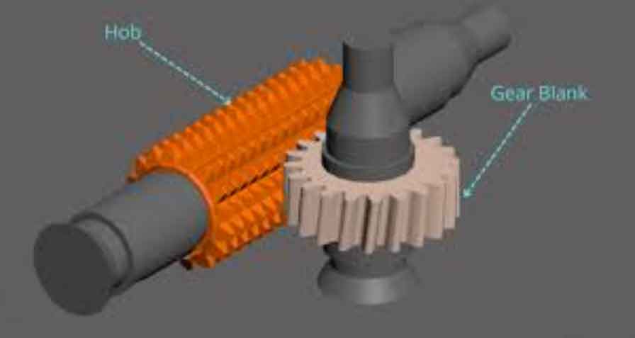
Hob geometry follows the rack-gear meshing principle. Coordinate transformation from gear system $O_1X_1Y_1$ to hob system $O_CX_CY_C$ yields hob tooth profile:
$$ \begin{pmatrix} X_C’ \\ Y_C’ \end{pmatrix} = \begin{pmatrix} X_1\cos\eta – Y_1\sin\eta + r_1\eta \\ X_1\sin\eta + Y_1\cos\eta – r_1 \end{pmatrix} $$
Hob parameters include: outer diameter 75mm, 12 flutes, 3 starts, helix angle 3.136°, and relief 5.4mm.
Workpiece Intermediate Geometry
Workpiece intermediate geometry is generated through Boolean operations between tool envelope surfaces and blank. Coordinate systems define relative motion:
| Coordinate System | Description |
|---|---|
| $O_rX_rY_rZ_r$ | Fixed reference |
| $O_1X_1Y_1Z_1$ | Tool reference |
| $O_2X_2Y_2Z_2$ | Workpiece reference |
The transformation matrix combines tool rotation $\mathbf{R_x}(\phi)$, axial feed $\mathbf{T_z}(\zeta(\phi))$, and workpiece rotation $\mathbf{R_z}(\psi(\phi))$:
$$ \mathbf{R}_{\text{trans}}(\phi) = \mathbf{R_z}(\psi(\phi)) \mathbf{T_z}(\zeta(\phi)) \mathbf{R_x}(\phi) $$
where $\zeta(\phi) = \frac{nf}{2\pi z}\phi$ and $\psi(\phi) = \pm \frac{z_0}{z}\phi$. The undeformed chip geometry between successive tool positions is:
$$ G_{i-1 \to i}(t,\phi) = \mathbf{R}_{\text{trans}}(\phi) E(t)_i – \mathbf{R}_{\text{trans}}(\phi) E(t)_{i-1} $$
Spatial tool trajectories at $\phi = 128\pi$ generate the tooth slot geometry through Boolean operations.
Thermo-Mechanical Finite Element Model
The gear hobbing simulation employs DEFORM-3D with material properties for 25CrMo4 cycloid gears and M35 hobs:
| Temperature (°C) | Young’s Modulus (MPa) | Thermal Expansion (×10⁻⁵/K) | Thermal Conductivity (W/m·K) | Specific Heat (J/kg·K) |
|---|---|---|---|---|
| 20 | 212,000 | 1.19 | 41.7 | 6.6189 |
| 100 | 207,000 | 1.25 | 43.4 | 3.8936 |
| 200 | 199,000 | 1.31 | 41.4 | 4.1841 |
| 300 | 192,000 | 1.36 | 39.1 | 4.4588 |
The Johnson-Cook constitutive model governs material behavior during gear hobbing:
$$ \sigma = \left( A + B\varepsilon^n \right) \left(1 + C \ln \frac{\dot{\varepsilon}}{\dot{\varepsilon_0}}\right) \left(1 – \left(\frac{T – T_{\text{room}}}{T_{\text{melt}} – T_{\text{room}}}\right)^m \right) $$
with fracture strain model:
$$ \varepsilon_D = \left[d_1 + d_2 \exp(-d_3\eta)\right] \left(1 + d_4 \ln \frac{\dot{\varepsilon}_{\text{pl}}}{\dot{\varepsilon_0}}\right) (1 + d_5 \hat{\theta}) $$
Model parameters: $d_1=0.1, d_2=0.76, d_3=1.57, n=0.2, C=0.02, m=0.64$. The mesh density is 0.01mm in deformation zones with oil cooling (convection coefficient 125 W/m²·K).
Gear Hobbing Simulation Results
Temporal Force/Temperature Evolution
At 600 rpm hob speed and 0.5 mm/r feed during gear hobbing:
| Phase | Axial Force | Radial Force | Temperature |
|---|---|---|---|
| Entry (0-2ms) | Rapid increase to 800N | Peak at 430N (1.6ms) | Rapid rise to 250°C |
| Stable (2-5ms) | 800N ±5% fluctuation | Gradual decrease | 250-290°C oscillation |
| Exit (5-7.1ms) | Rapid decrease | Continuous decrease | Stable decline |
Cutting force behavior correlates with shear zone area $A_s$:
$$ A_s \propto \sin^2\phi \sin^2\psi(\phi) \cos\psi(\phi) \cos\phi \cdot \zeta(\phi) + \cos^2\phi \cos^2\psi(\phi) \sin\psi(\phi) \sin\phi \cdot \zeta(\phi) $$
Parameter Effects in Gear Hobbing
Parameter effects were quantified through multiple gear hobbing simulations:
| Parameter Range | Axial Force Change | Radial Force Change | Temperature Change |
|---|---|---|---|
| Hob speed 300→900 rpm | 791N→834N (+5.4%) | – | 229°C→274°C (+19.7%) |
| Feed 0.25→0.75 mm/r | 803N→823N (+2.5%) | 324N→407N (+25.6%) | 225°C→244°C (+8.4%) |
| Feed 0.75→1.00 mm/r | 823N→914N (+11.1%) | 407N→554N (+36.1%) | 244°C→273°C (+11.9%) |
Feed influence dominates axial force generation in gear hobbing. The force differential between feed and speed effects is significant:
$$ \Delta F_{\text{axial}}|_{\text{feed}} = 91\text{N} > \Delta F_{\text{axial}}|_{\text{speed}} = 43\text{N} $$
Temperature sensitivity differs between parameter ranges:
$$ \frac{\partial T}{\partial v} = \begin{cases} 0.02^\circ\text{C/rpm} & (300-450 \text{rpm}) \\ 0.1^\circ\text{C/rpm} & (450-900 \text{rpm}) \end{cases} $$
$$ \frac{\partial T}{\partial f} = \begin{cases} 25.3^\circ\text{C/mm} & (0.25-0.75 \text{mm/r}) \\ 116^\circ\text{C/mm} & (0.75-1.00 \text{mm/r}) \end{cases} $$
Conclusions
1. During cycloid gear hobbing, axial force exhibits rapid growth, stabilization, and sharp decline phases. Radial force peaks early then gradually decreases. Temperature rises rapidly before stabilizing between 250-290°C during continuous cutting.
2. Axial feed significantly impacts forces in gear hobbing: below 0.75 mm/r, force increases remain below 25%, while exceeding this threshold causes force increments exceeding 36%. Hob speed variation affects axial force less substantially (<6% change).
3. Temperature sensitivity during gear hobbing shows critical thresholds: hob speed above 450 rpm accelerates temperature rise (0.1°C/rpm), while feeds beyond 0.75 mm/r triple temperature increase rates versus lower feeds.
4. For temperature-sensitive gear hobbing applications, axial feed should be maintained ≤0.75 mm/r. Productivity improvements should prioritize increased hob speed rather than feed augmentation to minimize thermal impact on gear accuracy.
These findings provide parameter optimization guidelines for precision manufacturing of cycloid gears through gear hobbing processes, balancing efficiency with thermal and mechanical constraints.