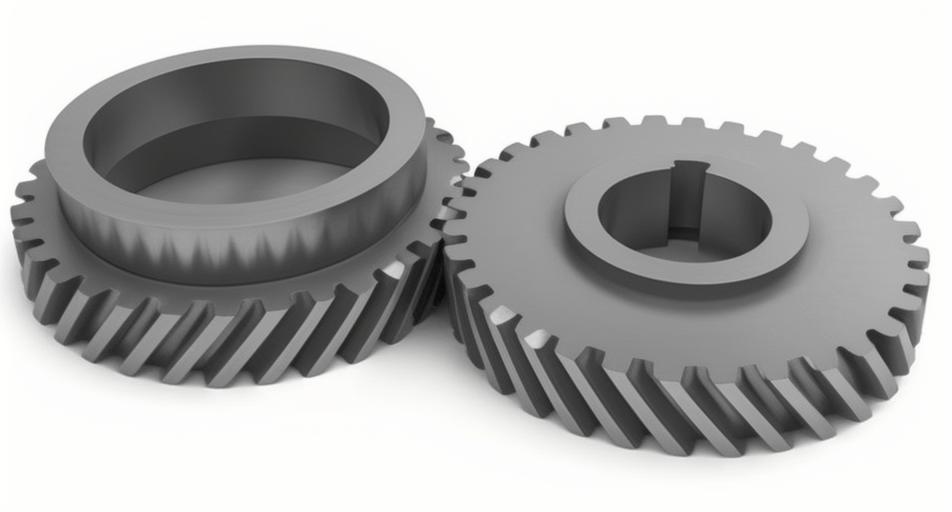
Helical gears are fundamental components in many mechanical systems due to their ability to transmit power efficiently and smoothly. Understanding the stress distribution within helical gears under variable loads is crucial for optimizing their design and ensuring their reliability. Finite Element Analysis (FEA) is a powerful computational tool that allows engineers to simulate and analyze the stress distribution in helical gears. This article delves into the application of Finite Element Analysis in studying helical gear stress distribution under variable loads, discussing the methodology, results, and implications for gear design.
Importance of Analyzing Stress Distribution in Helical Gear
- Load Capacity: Understanding stress distribution helps in designing helical gear that can handle higher loads without failure.
- Fatigue Life: Accurate stress analysis allows for predicting the fatigue life of helical gear, leading to improved reliability.
- Material Optimization: Identifying high-stress areas helps in optimizing material usage, potentially reducing costs.
- Design Improvements: Insights from stress distribution analysis can guide modifications to improve helical gear performance and longevity.
Methodology of Finite Element Analysis in Helical Gear Analysis
- Model Creation:
- Geometry: The first step is creating a precise geometric model of the helical gear using CAD software.
- Mesh Generation: The geometric model is divided into small finite elements (meshing). A finer mesh in high-stress areas ensures more accurate results.
- Material Properties:
- Define the material properties of helical gear, including Young’s modulus, Poisson’s ratio, and yield strength.
- Boundary Conditions:
- Apply appropriate boundary conditions to the model, such as fixed supports and rotational constraints.
- Loading Conditions:
- Apply variable loads that helical gear would experience in real-world scenarios. This includes both static and dynamic loads.
- Simulation and Analysis:
- Run the Finite Element Analysis simulation to compute the stress distribution within helical gear.
- Analyze the results to identify areas of high stress concentration.
Results and Discussion
Stress Distribution Patterns
Finite Element Analysis results typically reveal the following stress distribution patterns in helical gear:
- Root Stress:
- High stress concentration is usually observed at the root of helical gear teeth due to the bending moment.
- Contact Stress:
- The area where helical gear teeth come into contact exhibits significant stress due to the transmitted load.
- Tip Stress:
- Stress at the tip of the teeth is generally lower compared to the root but can still be significant under high loads.
Case Study: Variable Load Conditions
Scenario: An industrial helical gear system subjected to variable loads due to changing operational conditions.
Load Conditions:
- Low Load: 50 Nm
- Medium Load: 100 Nm
- High Load: 150 Nm
Finite Element Analysis Results:
| Load Condition | Maximum Root Stress (MPa) | Maximum Contact Stress (MPa) | Maximum Tip Stress (MPa) |
|---|---|---|---|
| Low Load | 120 | 200 | 80 |
| Medium Load | 240 | 400 | 160 |
| High Load | 360 | 600 | 240 |
Analysis:
- Root Stress: Increases proportionally with load, highlighting the need for strong material at the root.
- Contact Stress: Significantly higher than root and tip stress, indicating critical areas for wear.
- Tip Stress: Also increases with load but is lower compared to root and contact stress.
Design Implications
- Material Selection:
- Choose materials with high fatigue strength and wear resistance to withstand high contact stresses.
- Tooth Profile Modification:
- Implementing profile modifications like tip relief and root filleting can reduce stress concentrations.
- Heat Treatment:
- Apply surface hardening techniques, such as carburizing or nitriding, to improve surface hardness and reduce wear.
- Lubrication:
- Use high-performance lubricants to minimize friction and wear at the contact points.
List of Best Practices for Finite Element Analysis in Helical Gear Analysis
- Accurate Geometry: Ensure precise geometric modeling for reliable results.
- Fine Meshing: Use finer meshes in high-stress areas to capture detailed stress patterns.
- Material Data: Utilize accurate material properties for realistic simulations.
- Load Scenarios: Simulate a range of load conditions to understand helical gear behavior under different operational stresses.
- Validation: Validate Finite Element Analysis results with experimental data or empirical formulas.
Conclusion
Finite Element Analysis (FEA) is an indispensable tool for understanding and optimizing the stress distribution in helical gear under variable loads. By accurately modeling helical gear geometry, applying realistic load conditions, and analyzing the resulting stress patterns, engineers can make informed decisions to enhance helical gear design, material selection, and overall performance.
The insights gained from FEA enable the development of helical gear that are not only more efficient but also more reliable and durable, ultimately leading to cost savings and improved operational performance. As technology advances, the integration of Finite Element Analysis with other simulation tools and experimental methods will continue to push the boundaries of helical gear design and engineering.
Table: Summary of Key Findings
| Aspect | Finding | Design Recommendation |
|---|---|---|
| Root Stress | High under all load conditions | Use high-strength materials, implement root relief |
| Contact Stress | Highest stress observed at contact points | Use wear-resistant materials, ensure proper lubrication |
| Tip Stress | Lower than root and contact stress but significant | Implement tip relief if necessary |
| Variable Load Impact | Stress increases proportionally with load | Design for the highest expected load |
List: Key Benefits of Finite Element Analysis in Helical Gear Analysis
- Precision: Provides detailed insights into stress distribution.
- Efficiency: Helps in optimizing helical gear design for better performance.
- Cost Savings: Reduces the need for extensive physical testing.
- Reliability: Enhances the reliability and longevity of helical gear systems.
In summary, the application of Finite Element Analysis in studying the stress distribution of helical gear under variable loads is a critical process that aids in designing high-performance, durable, and reliable gears for industrial applications. By leveraging the power of Finite Element Analysis, engineers can ensure that helical gears meet the demanding requirements of modern machinery.l
