1. Finite element modeling of helical gears
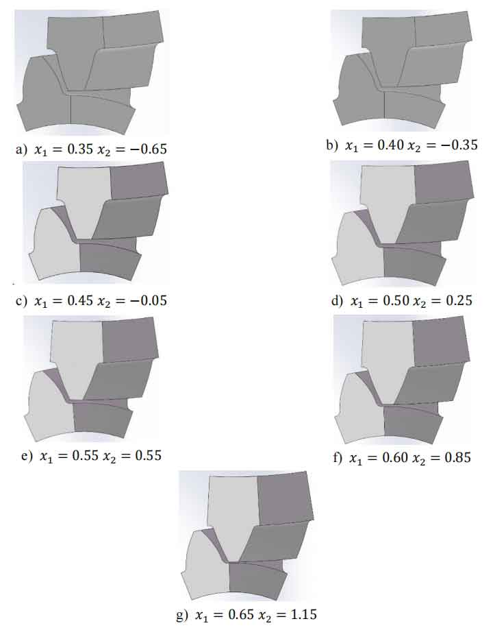
The results of transient dynamic finite element analysis indicate that the maximum bending stress at the tooth root of the helical gears pair in the two tooth meshing zone is greater than that in the three tooth meshing zone. The focus of this chapter is on the bending fatigue life of helical gears, so static analysis is more practical compared to transient dynamic simulation. Static analysis only requires the establishment of a single tooth meshing finite element model, so it is necessary to establish single tooth finite element models with different modification coefficients for both wheel and pinion gears for subsequent calculations. The parameters of different helical gears modification coefficients are shown in Table 1.
| Pinion gear displacement coefficient 𝑥1 | Wheel gear modification coefficient 𝑥2 |
| 0.35 | -0.65 |
| 0.40 | -0.35 |
| 0.45 | -0.05 |
| 0.50 | 0.25 |
| 0.55 | 0.55 |
| 0.60 | 0.85 |
| 0.65 | 1.15 |
Firstly, use the Geartrax plugin to establish helical gear pairs with different modification coefficients. Then divide the established model into segments, retain one meshing single tooth each for the wheel and pinion gears, assemble them, and inspect the model to ensure no interference for subsequent static analysis. The single tooth meshing model is shown in Figure 1.
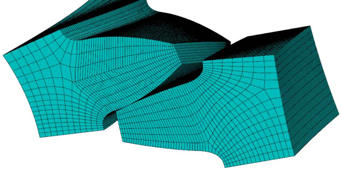
Taking the single tooth meshing model with 𝑥 1=0.35 and 𝑥 2=− 0.65 as an example, after meshing, as shown in Figure 2, the number of nodes is 108557 and the number of elements is 96751.
2. Load analysis of single tooth meshing model
Based on the finite element model calculation results and the principle of helical gears meshing, applying torque to the helical gears pinion can accurately simulate the working state of helical gear meshing, and calculate the stress distribution and magnitude of the gear teeth that are in line with the actual situation. The torque magnitude loaded on the helical gears pinion can be expressed as:
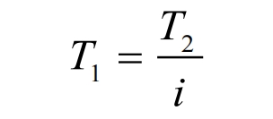
In the formula, 𝑇 1 is the torque of pinion gear, 𝑇 2 is the torque of the wheel gear, and i is the helical gears transmission ratio. The torque 𝑇𝑠𝑚 applied by a single pair of tooth meshing models can be calculated by the following formula:
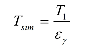
In the formula, 𝜀𝛾 is the coincidence degree of the helical gears pair, and the expression is as follows:

In the formula, 𝜀𝛼 is the end face coincidence degree, 𝜀𝛽 is the longitudinal coincidence degree, and the end face coincidence degree 𝜀𝛼 can be calculated by the following formula:
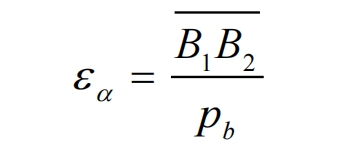
In the formula, 𝐵1𝐵\2 ̅̅̅̅̅̅̅ For the actual length of the meshing line, 𝑝𝑏 is the base tooth pitch. Due to the change in overlap during the meshing process of helical gears, in order to ensure the safety and reliability of the helical gears pair transmission, the end face overlap 𝜀𝛼 should be taken as the maximum value during the variation process, which can be calculated by the following formula:

In the formula, 𝜀𝑎 1 and 𝜀𝑎 2 can be calculated by the following equation:

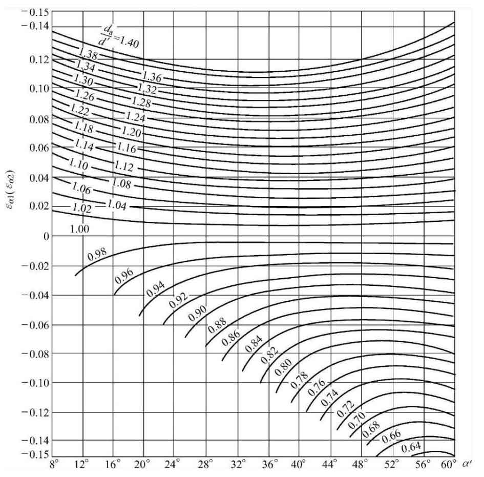
The value of 𝜀𝑎 is only related to the tooth top pressure angle 𝛼𝑎 and the meshing angle 𝛼′, and is independent of the number of teeth. The tooth top pressure angle 𝛼𝑎 can be calculated by the following equation:

So for a certain meshing angle 𝛼, 𝜀𝑎 can be found based on the ratio of tooth tip diameter 𝑑𝑎 and pitch circle diameter 𝑑𝑎 in Figure 3 of this chapter according to the figure in “Involute Cylindrical Gear Transmission”.
The vertical overlap degree 𝜀𝛽 can be calculated by the following equation:

As can be seen from the above equation, the larger the helix angle 𝛽 and tooth width b of the helical gear sindexing circle, the greater the overlap of the helical gears. According to the formula, the loading data of the single tooth meshing finite element model can be calculated as shown in Table 2.
| Gear pair x1 | End face overlap degree 𝜀𝛼 | Vertical overlap degree 𝜀𝛽 | Gear pair overlap ratio 𝜀𝛾 | Torque 𝑇𝑠𝑚 (𝑁· 𝑚) |
| 0.35 | 1.5040 | 1.0363 | 2.5403 | 2304.1 |
| 0.40 | 1.4496 | 1.0363 | 2.4859 | 2354.5 |
| 0.45 | 1.4180 | 1.0363 | 2.4543 | 2384.9 |
| 0.50 | 1.4023 | 1.0363 | 2.4386 | 2400.2 |
| 0.55 | 1.3987 | 1.0363 | 2.4350 | 2403.8 |
| 0.60 | 1.4041 | 1.0363 | 2.4404 | 2398.5 |
| 0.65 | 1.4167 | 1.0363 | 2.4530 | 2386.1 |
3. Verification and Analysis of Finite Element Model Accuracy
Prove that GB/T 3480 has high accuracy. In order to verify whether the single tooth meshing finite element model can obtain sufficiently accurate results, the calculated values in the national standard GB/T 3480 for calculating the load-bearing capacity of helical gears were compared with the simulation analysis values through the single tooth meshing finite element model, in order to verify whether the model can be used for calculating the root stress of helical gears.
The tooth root stress 𝜎 F is the maximum tensile stress at the surface of the tooth root fillet. According to GB/T 3480 “Calculation of Load Capacity of Spur and Helical Gears”, the tooth root stress 𝜎 F can be calculated by the following formula:

In the formula, KA is the utilization coefficient, which can be selected based on the working characteristics of the working machine and the prime mover. For subway operation conditions, the utilization coefficient KA takes a value of 1.2; KV is the dynamic load coefficient, considering the influence of manufacturing accuracy and pitch line speed of helical gears. The precision level of the helical gears pair studied in this chapter is 6, and according to GB/T 3480, the dynamic load coefficient Kv is taken as 1.2; 𝐾𝛽 is the tooth load distribution coefficient, calculated according to GB/T 3480, with a value of 1.21 for 𝐾𝛽; 𝐾𝛼 is the load distribution coefficient between teeth. For the helical gears pair studied in this chapter, according to GB/T 3480, the value is 1.
There are two calculation methods for the basic tooth root stress 𝜎 F0. The first method is based on the load acting on the meshing area of a single pair of teeth. The tooth root stress can be calculated using the following formula:
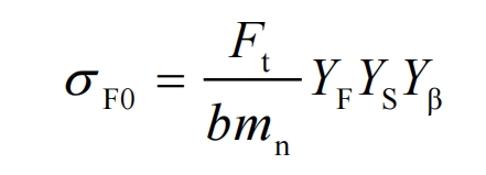
In the formula, 𝐹𝑡 is the nominal tangential force on the end face; B is the working tooth width. For gears with different widths, the working tooth width of a wider helical gears is the width of a narrower helical gears plus a modulus; 𝑌𝐹 is the tooth profile coefficient; 𝑌𝑆 is the stress correction coefficient; 𝑌𝛽 is the helix angle coefficient.
The second method is based on the calculation of the load acting on the tooth tip area, and is only applicable to helical gears transmissions with 𝜀𝛼<2. The calculation method can be as follows:

In the formula, 𝑌𝐹𝑎 is the tooth profile coefficient when the load acts on the tooth tip; 𝑌𝑆𝑎 is the stress correction coefficient when the load acts on the tooth tip; 𝑌𝜀 is the overlap coefficient.
The structure of the helical gears pair meets the requirements of Method 2. However, because the finite element analysis object in this chapter is a model of a single pair of gear teeth meshing, and Method 1 is more suitable for situations where the calculation accuracy of the helical gears is required to be higher, in order to ensure that the subway transmission helical gears does not affect the safety of subway operation, the first method in GB/T 3480 is used to verify the accuracy of the finite element model in this chapter. In the first method, the tooth profile coefficient 𝑌𝐹 and the stress correction coefficient 𝑌𝑆 can be calculated according to the formula.
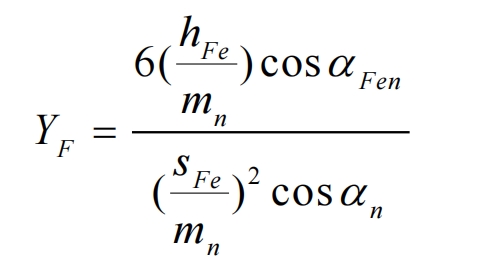
In the formula, 𝑚𝑛 is the normal modulus of the helical gears; 𝛼𝑛 is the normal pressure angle; Other required parameters such as 𝛼𝐹𝑒𝑛, ℎ𝐹𝑒, 𝑠𝐹𝑛, etc. shall be calculated according to the formulas in the table of GB/T 3480.

In the formula, 𝑞𝑠 is the root fillet parameter, which can be calculated by the following equation:
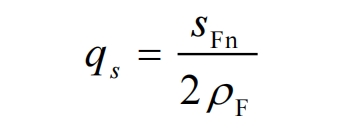
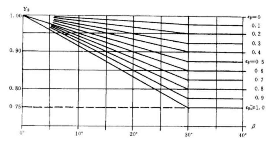
The helix angle coefficient 𝑌𝛽 when the load acts on the meshing area of a single pair of teeth can be obtained from the figures in GB/T 3480 and Figure 4 based on the helix angle 𝛽 and longitudinal overlap 𝜀𝛽.
Taking the model with a wheel gear modification coefficient of -0.65 and pinion gear modification coefficient of 0.3 as an example, the basic values of tooth root stress 𝜎 F0 and tooth root stress 𝜎 F were calculated according to the formula. The parameters and calculation results are shown in Table 3.
| Parameter | Spiral angle 𝛽 (°) | Nominal tangential force 𝐹𝑡 (kN) | Tooth shape coefficient 𝑌𝐹 | Stress correction coefficient 𝑌𝑆 | Spiral angle coefficient 𝑌𝛽 | Basic tooth root stress 𝜎𝐹 0 (MPa) | Root stress 𝜎𝐹 (MPa) |
| Pinion gear | 19 | 42.67 | 2.38 | 1.77 | 0.83 | 376.72 | 656.40 |
| Wheel gear | 19 | 42.67 | 2.65 | 1.58 | 0.83 | 427.93 | 745.63 |
The comparison between the static finite element analysis results of the helical gears single tooth meshing model with a modification coefficient 𝑥 1=0.35 𝑥 2=− 0.65 and the calculation results according to GB/T 3480 is shown in Table 4. It can be seen that for this pair of helical gears with modification coefficients, the root stress obtained from the finite element static analysis of single tooth meshing of the pinion gear is 649MPa, which is smaller than the root stress calculated according to GB/T 3480, which is 656.4MPa, and the difference is only 1.127%; The tooth root stress obtained from the finite element static analysis of the single tooth meshing of the wheel gear is 785.8MPa, which is larger than the tooth root stress calculated according to GB/T 3480, which is 745.63MPa, with a difference of only 5.387%. This can prove that the single tooth meshing finite element model established in this chapter can be used for calculating the root stress of helical gears, for subsequent analysis of the bending fatigue life of helical gear pairs.
| Root stress 𝜎𝐹 | Finite element results (MPa) | Calculation result (MPa) | Error |
| Pinion gear | 649.00 | 656.40 | -1.127% |
| Wheel gear | 785.80 | 745.63 | 5.387% |
4. Stress analysis results of helical gears with different modification coefficients
ABAQUS software is a professional finite element analysis software that can solve complex simulation problems. According to the verification results, ABAQUS software can accurately perform static analysis on the finite element model established in this chapter.
First, import the single tooth meshing model shown in Figure 1 into ABAQUS software and perform preprocessing. Set completely fixed boundary conditions for the wheel gear single tooth finite element model, and set fixed boundary conditions for the pinion gear single tooth finite element model with other degrees of freedom except for z-axis rotation (helical gear rotation axis). Set the pinion gear meshing torque according to the data in Table 2, and finally submit the task. The stress analysis results of the single tooth meshing model of helical gears with different modification coefficients are shown in Figures 5 to 11.
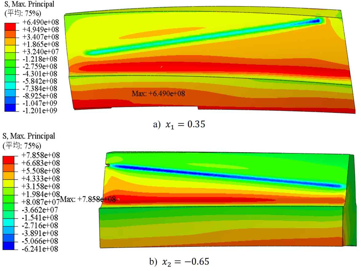
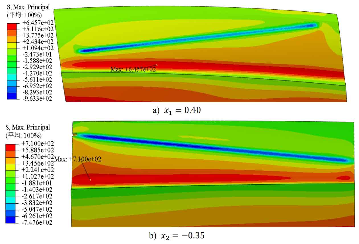
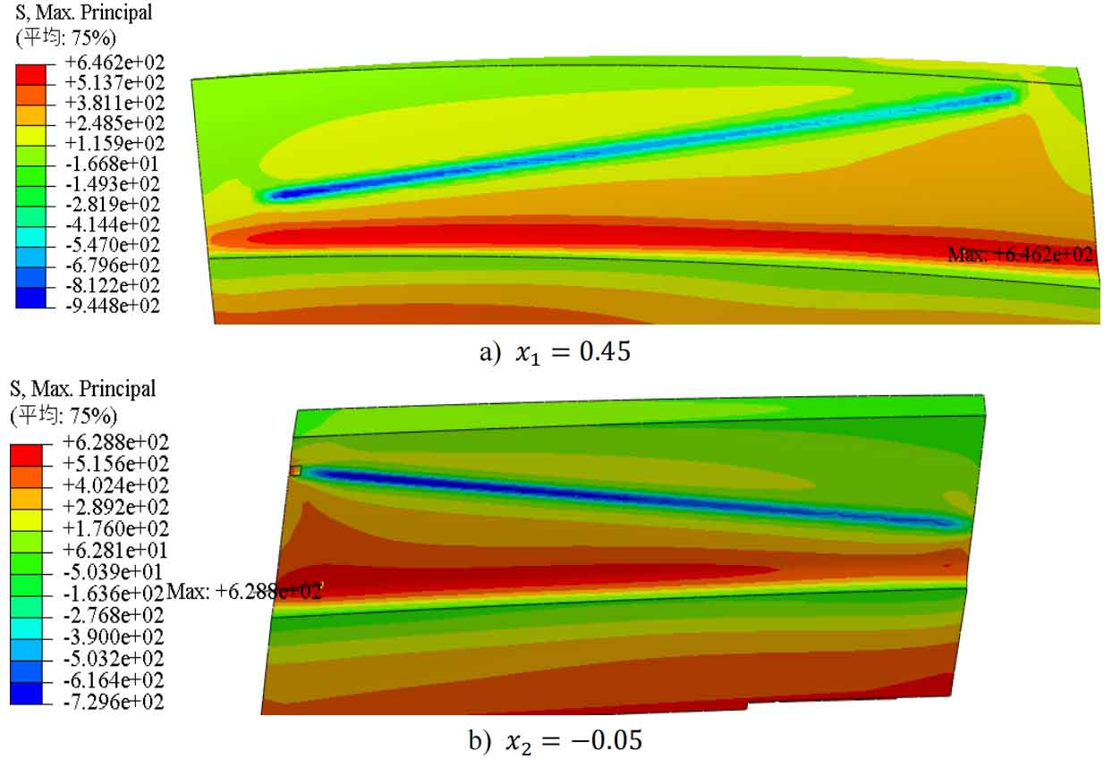
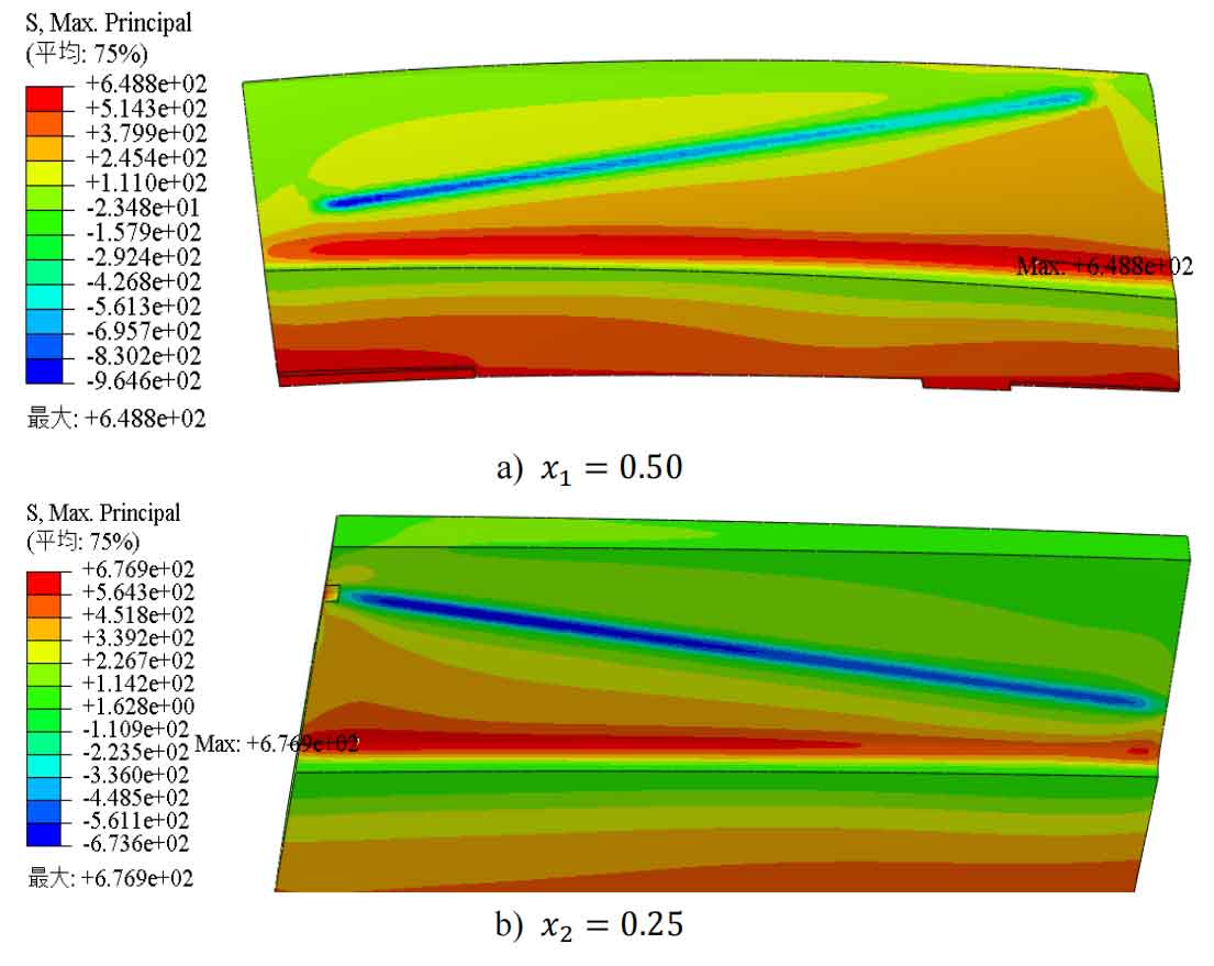
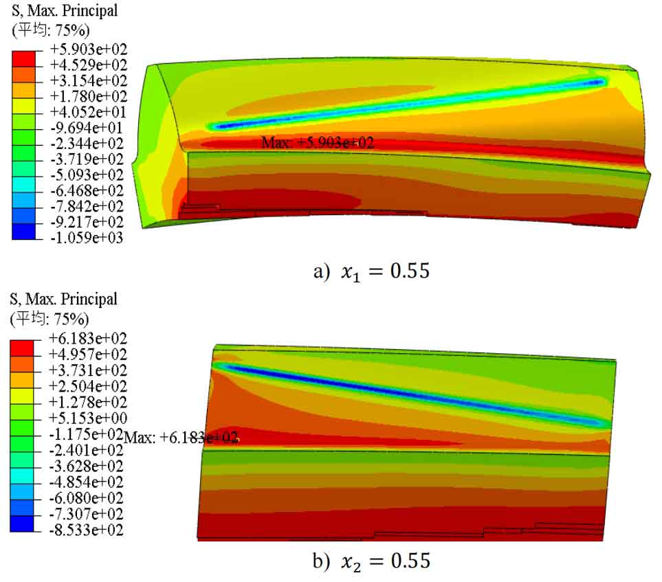
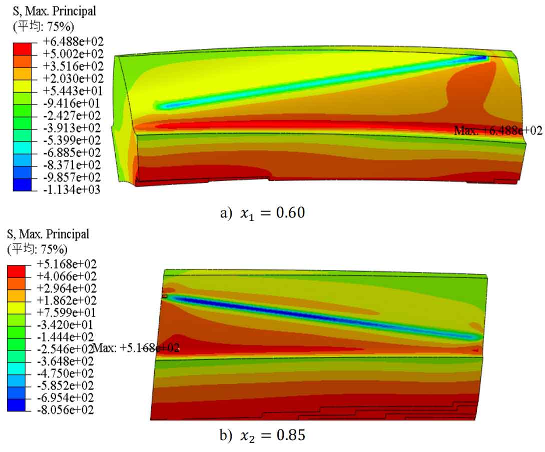
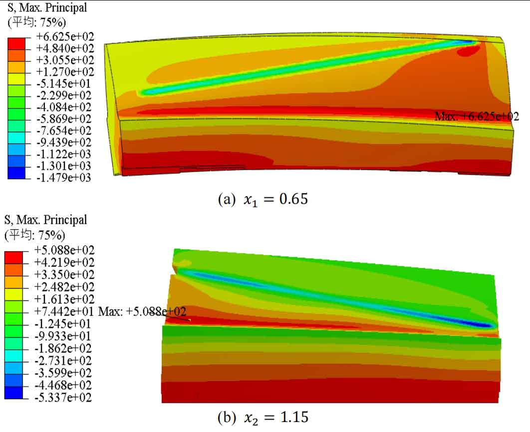
From Figures 5 to 11, it can be seen that when the modification coefficient changes from small to wheel within the selected range, the root stress of the pinion gear will first decrease to a certain value and then increase, while the root stress of the wheel gear will first decrease to a certain value and then slightly increase to a certain value before decreasing again. The maximum stress at the tooth root of wheel gear is always at the tooth root position that is farthest from the meshing line to the tooth root. There are two situations where the maximum stress at the tooth root of the pinion gear occurs: one is at the tooth root position farthest from the meshing line to the tooth root, and the other is at about one-third of the distance from the closest end to the tooth root to the farthest end of the meshing line.
