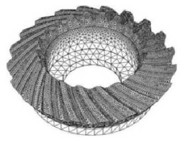
The 3D models of nutation inner and outer bevel gears are imported into the finite element analysis software and assembled. The internal and external bevel gears are made of structural steel, the elastic modulus is 210 GPA, Poisson’s ratio is 0.3, and the material density is 7 850 kg / m3. In order to ensure the solution accuracy and save calculation time, the seed global size of bevel gear tooth and gear blank is set to 1 and 4 respectively, and a 10 node quadric tetrahedral element mesh is generated by using free mesh generation. The mesh division of outer bevel gear is shown in Fig. 1. According to the motion principle of the single-stage nutation transmission mechanism, hinge connection is used between the bevel shaft and the outer bevel gear, which limits the freedom degrees of the outer bevel gear blank in five directions except the rotation around the axis direction of the inclined axis, and all the degrees of freedom of the inner bevel gear blank. According to the design requirements of the transmission power and speed of the reducer, the input shaft speed is 3 000 R / min, and the load torque on the output shaft is 636 n · M. The tooth contact mode of internal and external bevel gears is set as hard contact and limited slip, and explicit solver is selected. The total time of finite element loading analysis is 1 s, which is divided into 100 incremental steps.
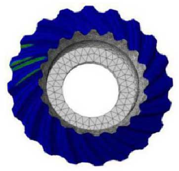
The tooth surface contact area of nutation bevel gear can be obtained by finite element analysis, and the tooth surface contact area curve can be drawn by the value of the last 50 incremental steps (i.e. 0.5 ~ 1 s time period) with stable transmission, as shown in Fig. 2. The maximum contact area of tooth surface is 98 mm 2 and the average value is 42.8 mm 2. At the same time, according to the contact pressure diagram of the tooth surface shown in Fig. 3, when the inner and outer double circular arc nutation bevel gears are engaged, because there are multiple teeth engaging at the same time, and there is a meshing contact trace on the concave and convex tooth surfaces of one of the teeth, the contact surface area of the tooth surface is larger, so that the load is dispersed and the transmission is more stable.
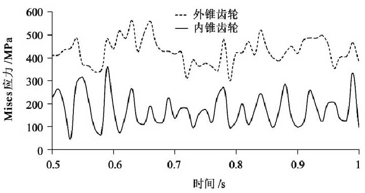
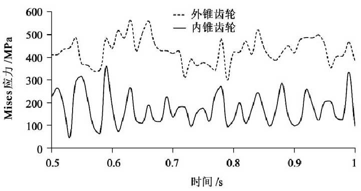
The maximum Mises stress curve of nutation bevel gear in 0.5 ~ 1 s is shown in Fig. 4. Fig. 5 shows the Mises stress nephogram of nutation inner and outer bevel gears at 0.95 s.
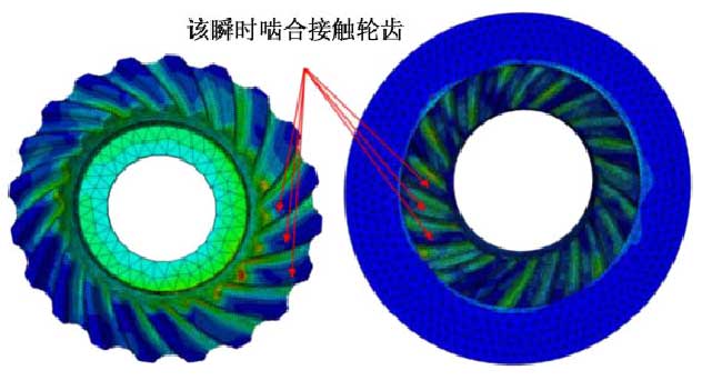
As shown in Fig. 4, the maximum Mises stress of the outer bevel gear is larger than that of the inner bevel gear at each time. The reason is that the maximum Mises stress of the outer bevel gear is mostly located at the top of the small end of the tooth, as shown in Fig. 5. Because the thickness of the tooth at the top of the small end tooth is small and the structural shape is abrupt, the stress value is large. But on the whole, the Mises stress is evenly distributed on the whole tooth surface of the inner and outer bevel gears.
