
1.Load stroke curve
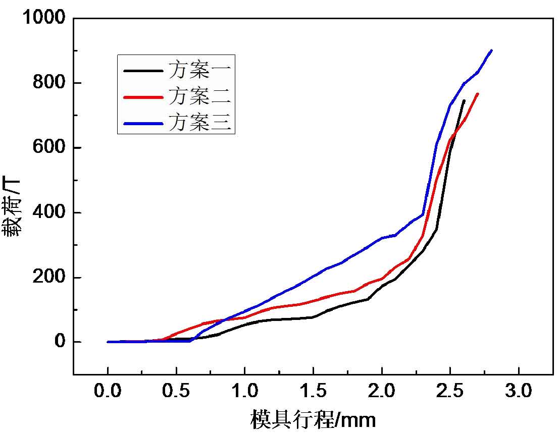
Figure 1 shows the load stroke curve of hot die forging process of different taper schemes of spiral bevel gear blank. The load stroke trend of each scheme is basically the same: in the first stage, the tooth die first contacts the small end of the spiral bevel gear blank, and the load growth amplitude is small; In the second stage, the tooth shape die contacts the tooth top of the spiral bevel gear blank, the die extrudes the blank metal, and the deformation resistance of the spiral bevel gear blank increases, so the load growth speed is accelerated; In the third stage, the central area of the tooth root direction of the spiral bevel gear blank is basically formed, and the material flow direction is changed to fill the two ends of the tooth shape of the die and the edges and corners of the tooth root; Finally, the tooth profile is formed. Forming load of each scheme: scheme 1 is 746t; Scheme II is 766T; Scheme III reached about 910t. As the taper of spiral bevel gear blank decreases, the hot die forging load of spiral bevel gear blank increases.
2.Material flow analysis
The starting point of studying the influence of spiral bevel gear blank with different taper on hot die forging process is to try our best to complete the forming of large end and small end of tooth profile at the same time. Therefore, it is very important to observe the material flow in the forming process of each taper scheme to select the appropriate taper spiral bevel gear blank.
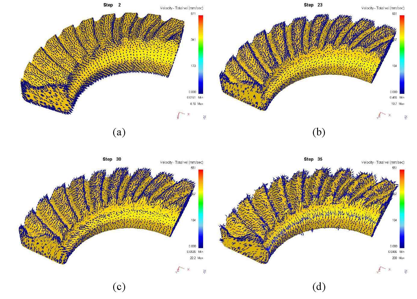
Fig. 2 (a) ~ (d) is the schematic diagram of material flow in the forming process of scheme I in turn. Firstly, the tooth die is in contact with the small end of the tooth, the blank has pier coarsening effect and the material flows radially; With the increase of the die stroke, the contact area between the die and the workpiece increases continuously. The tooth top part of the tooth die contacts both sides of the tooth root of the spiral bevel gear blank, and the blank metal is extruded and flows to the tooth height direction; Then, the space in the corner opposite to the spiral angle of the tooth root part of the tooth model cavity is filled first, and then the other side is filled; The die is further pressed down and the material flows to the small end of the tooth shape. The taper of spiral bevel gear blank in scheme 1 is 1 ° smaller than the taper angle of tooth profile die root. Because the taper change is too small, the metal flow process in scheme 1 is roughly similar to that when the taper of spiral bevel gear blank is equal to that of die, and the effect is not good.
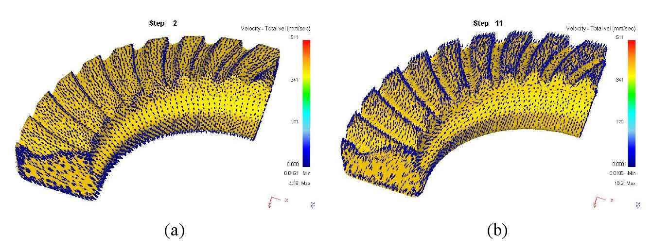

Fig. 3 (a) ~ (d) is the schematic diagram of material flow in the forming process of scheme 2 in turn. The taper of spiral bevel gear blank in scheme 2 is 3 ° smaller than the root cone angle of the die. Different from scheme 1, the spiral bevel gear blank in scheme 2 basically fills the gap at the tooth root of the die (corresponding to the tooth top of the spiral bevel gear blank), and the material flows to both sides of the large end and small end of the tooth shape at the same time until the end of the die stroke. This scheme achieves the goal of studying the blank taper in this section to realize the simultaneous forming of the large end and small end of the tooth shape, and there is no burr at the radial boss of the spiral bevel gear blank, and there is no metal accumulation at both ends of the tooth shape.
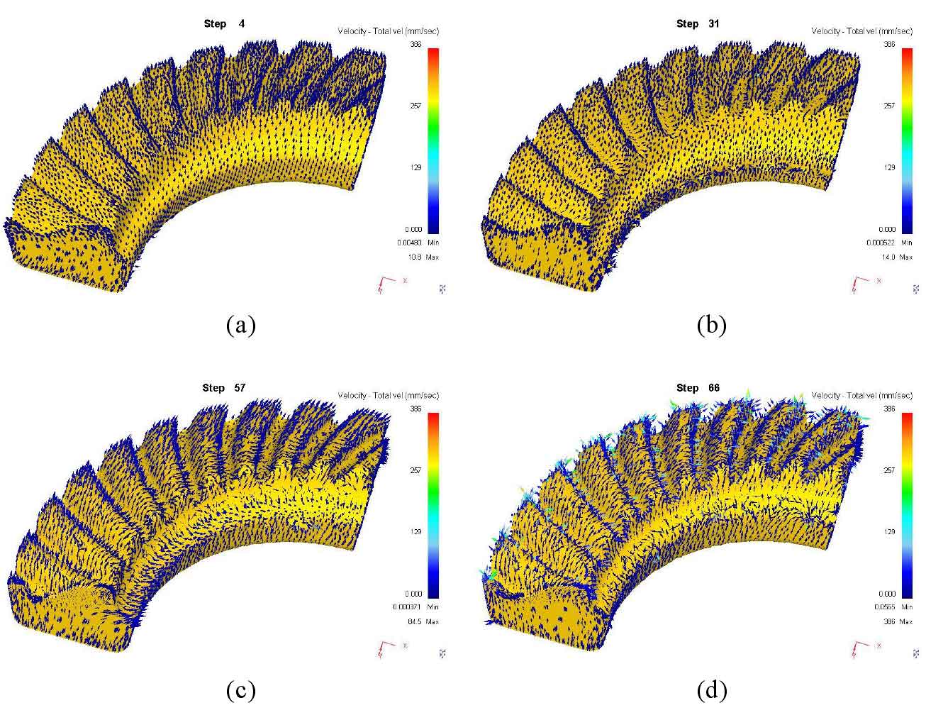
Fig. 4 (a) ~ (d) is the schematic diagram of material flow in the forming process of scheme 3. In scheme 3, the taper of spiral bevel gear blank is less than the taper angle of tooth profile die root by 5 °. The smaller the taper, the higher the height of the spiral bevel gear blank, the stroke of the die increases, and the local material flow is more intense. The stress concentration and burr formed at the edge of the boss of the inner diameter of the spiral bevel gear blank early; Moreover, in the final stage of the forming scheme, the metal accumulation is also formed on the outside of the large end of the tooth shape of the spiral bevel gear blank due to the obstruction of local metal flow. The unreasonable material flow resulted in a significant increase in the die load of the scheme.
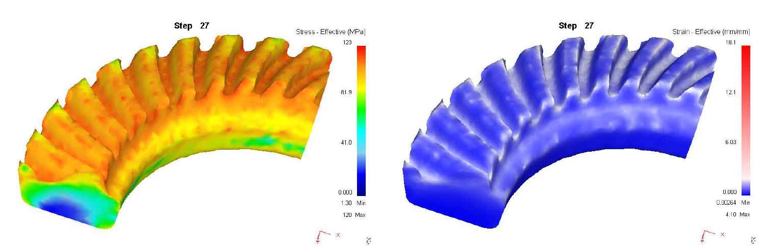
Figure 5 shows the distribution of equivalent stress and equivalent strain at the end of hot die forging of spiral bevel gear blank in scheme 2. It can be seen from the figure that the equivalent stress distribution of spiral bevel gear blank in scheme 2 is uniform, and there is no stress concentration; The equal effect variation at the tooth top and both sides of the tooth root is large, indicating that the local material flow is intense and the plastic flow is good.
Through the analysis and comparison of the material flow process of the above three schemes, it is not difficult to find that scheme II (taper of spiral bevel gear blank) β Specific tooth profile die root cone angle α Small 3 °) not only the stress distribution is uniform, there are no burrs and other defects in some parts, and the plastic flow of the material is good, but also the simultaneous forming of both sides of the large and small ends of the tooth profile is realized, which achieves the expected goal of studying the taper of spiral bevel gear blank. The optimum taper of the preform for closed hot die forging of spiral bevel gear is determined to be 3 ° less than the taper angle of the tooth form die root.