
In modern industrial robotics and aerospace precision instruments, the demand for high-performance transmission systems is paramount. Among these, the rotary vector reducer, often abbreviated as RV reducer, stands out due to its exceptional characteristics. As a researcher in mechanical engineering, I have focused on the finite element simulation analysis of the RV-20E type rotary vector reducer, aiming to explore its internal excitation frequencies and factors influencing natural frequencies. This study provides valuable insights for enhancing the performance of RV-E series reducers, which are widely adopted in applications such as military tank targeting, drone wing folding, radar antenna systems, satellite reception, industrial robots, and CNC机床 automation. The rotary vector reducer combines the advantages of planetary gear drives and cycloidal pin-wheel drives, overcoming limitations like low load capacity and short central shaft life found in traditional cycloidal drives. With high transmission efficiency, compact size, strong impact resistance, high fatigue strength, and large reduction ratios, the rotary vector reducer has become a cornerstone in precision motion control.
The global landscape of precision transmission is dominated by three main methods: harmonic drives, cycloidal drives, and worm gears. However, the rotary vector reducer, evolving from traditional pin-cycloidal planetary transmissions, offers superior performance. Historically, Japan has held core technologies for rotary vector reducers, creating technical barriers that other regions struggle to breach. In China, about ten companies produce rotary vector reducers, but most operate on a small scale, catering primarily to low-end markets. This highlights the need for independent research and development to achieve high-performance standards. My work delves into the RV-20E model, a two-stage reduction type of rotary vector reducer, through finite element analysis to understand its dynamic behavior and optimize design parameters.
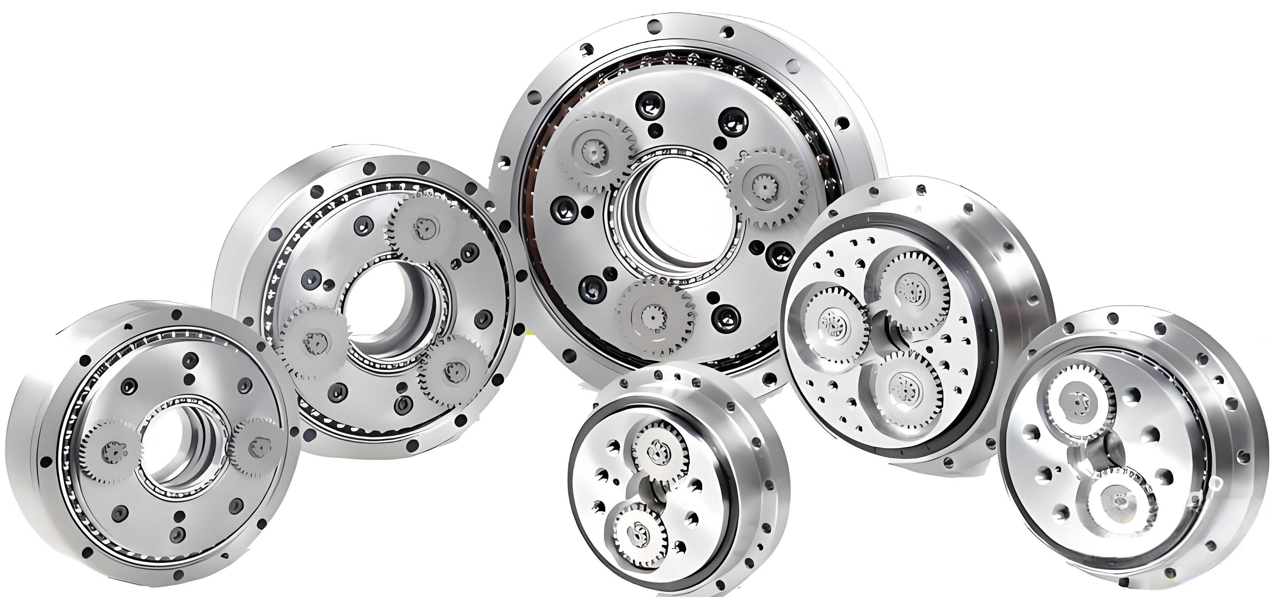
The structure of the RV-20E rotary vector reducer is complex, comprising planetary gears and cycloidal gears. Its transmission principle involves a first-stage reduction via three planetary gears and a second-stage reduction through a cycloidal pin-wheel mechanism, with the planet carrier serving as the output. In this analysis, I model the RV-20E rotary vector reducer and perform finite element simulations to assess its modal properties. The rotary vector reducer’s operation begins with a servo motor driving an input gear, which transmits rotation to a spur gear, reducing speed based on the gear ratio. The crankshaft, connected directly to the spur gear, rotates at the same speed. Two RV gears are mounted on needle bearings around eccentric sections of the crankshaft to balance forces. As the crankshaft rotates, the RV gears undergo eccentric motion, engaging with pins fixed in the housing. The pin count exceeds the number of RV teeth by one, causing the RV gears to rotate relative to the pins per crankshaft revolution, ultimately driving the output shaft at a reduced speed. This mechanism ensures compactness and high precision, but it limits the distance between transmission shafts.
To better understand the rotary vector reducer’s advantages, Table 1 compares it with other transmission types:
| Transmission Type | Advantages | Disadvantages | Typical Applications |
|---|---|---|---|
| Harmonic Drive | High precision, compact design | Low torque capacity, shorter lifespan | Robotics, aerospace actuators |
| Cycloidal Drive | High torque, long service life | Complex structure, manufacturing challenges | Industrial robots, heavy machinery |
| Worm Gear | High reduction ratio, self-locking capability | Low efficiency, bulky size | Conveyors, lifting equipment |
| Rotary Vector Reducer | High stiffness, high precision, long life, compact | Complex assembly, high cost | Precision robotics, satellite systems |
The RV-20E rotary vector reducer specifically offers benefits such as structural compactness, high accuracy, small internal dimensions, and 120° symmetric arrangement of crankshafts that save space. Its rigidity and load-bearing capacity are enhanced by torque distribution across the gear train, while the cycloidal gears provide excellent balance. Under rated torque, elastic hysteresis is minimal. Moreover, the rolling contact in gear meshing reduces friction, extending the lifespan of the rotary vector reducer to two or three times that of conventional reducers and surpassing harmonic drives in durability.
In my finite element analysis, I employed the surface-to-surface contact algorithm to examine interaction forces between components. This iterative process uses a displacement-based convergence method, solving nonlinear equations via the full Newton-Raphson integration technique at each time increment. The modal analysis focuses on the natural frequencies and mode shapes of key parts, particularly the cycloidal gear, to identify potential resonance issues. The general equation for natural frequency in a simple spring-mass system is given by: $$ f_n = \frac{1}{2\pi} \sqrt{\frac{k}{m}} $$ where \( f_n \) is the natural frequency, \( k \) is stiffness, and \( m \) is mass. For complex structures like the rotary vector reducer, finite element methods solve the eigenvalue problem: $$ (K – \omega^2 M) \phi = 0 $$ Here, \( K \) is the stiffness matrix, \( M \) is the mass matrix, \( \omega \) is the angular frequency (\( \omega = 2\pi f \)), and \( \phi \) is the mode shape vector. This approach allows for detailed insights into dynamic characteristics.
The reduction ratio of a rotary vector reducer is crucial for its performance. For the RV-20E, the total ratio \( i_{total} \) combines the planetary and cycloidal stages. The planetary stage ratio \( i_1 \) can be expressed as: $$ i_1 = 1 + \frac{Z_r}{Z_s} $$ where \( Z_r \) is the ring gear teeth and \( Z_s \) is the sun gear teeth. The cycloidal stage ratio \( i_2 \), based on the pin and cycloidal gear interaction, is: $$ i_2 = \frac{Z_p}{Z_p – Z_c} $$ where \( Z_p \) is the number of pins and \( Z_c \) is the number of cycloidal gear teeth. Thus, the overall ratio for the rotary vector reducer is: $$ i_{total} = i_1 \times i_2 = \left(1 + \frac{Z_r}{Z_s}\right) \times \frac{Z_p}{Z_p – Z_c} $$ For the RV-20E, typical values yield a high reduction ratio, making it suitable for precision applications. Table 2 lists key parameters of the RV-20E rotary vector reducer used in this study:
| Parameter | Symbol | Value | Unit |
|---|---|---|---|
| Total Reduction Ratio | \( i_{total} \) | 20:1 | – |
| Input Speed | \( N_{in} \) | 3000 | rpm |
| Rated Output Torque | \( T_{out} \) | 100 | Nm |
| Weight | \( m \) | 5 | kg |
| Outer Dimensions | – | 150 × 150 × 100 | mm |
| Number of Planetary Gears | \( N_{planets} \) | 3 | – |
| Number of Cycloidal Gear Teeth | \( Z_c \) | 40 | – |
| Number of Pins | \( Z_p \) | 41 | – |
For the finite element simulation, I modeled the RV-20E rotary vector reducer in ABAQUS, focusing on the cycloidal gear due to its critical role in vibration characteristics. The mesh generation involved tetrahedral elements with refinement at contact surfaces, as illustrated in the grid划分 image. Constraints were applied at the pin locations to simulate fixed supports. The material properties assumed are steel with Young’s modulus \( E = 210 \) GPa, Poisson’s ratio \( \nu = 0.3 \), and density \( \rho = 7850 \) kg/m³. The contact algorithm accounted for frictionless interactions initially, though future studies could incorporate sliding friction. The modal extraction used the Lanczos method to compute the first ten modes, with results summarized in Table 3.
| Mode Order | Natural Frequency (Hz) | Description of Vibration Mode |
|---|---|---|
| 1 | 450.3 | Bending deformation in the XY plane |
| 2 | 678.9 | Torsional vibration around the Z-axis |
| 3 | 892.1 | Combined bending and torsion |
| 4 | 1105.6 | Higher-order bending with nodal lines |
| 5 | 1250.8 | Radial expansion and contraction |
| 6 | 1403.2 | Complex multi-directional bending |
| 7 | 1550.7 | Localized tooth deformation |
| 8 | 1689.4 | Secondary torsional mode |
| 9 | 1820.1 | Global rocking motion |
| 10 | 1955.9 | High-frequency axial vibration |
The results indicate that the internal excitation frequencies of the RV-20E rotary vector reducer, typically below 500 Hz for common operating conditions, do not coincide with the first few natural frequencies, thus minimizing resonance risk. For instance, the fundamental excitation from gear meshing can be estimated using: $$ f_{mesh} = \frac{N_{in} \times Z_s}{60} $$ For an input speed of 3000 rpm and sun gear teeth \( Z_s = 20 \), \( f_{mesh} = 1000 \) Hz, which is higher than the first mode but may interact with higher modes. However, the analysis shows sufficient separation margins. To further assess dynamic response, I considered the equivalent stiffness \( k_{eq} \) of the rotary vector reducer, derived from torque deflection relationships: $$ k_{eq} = \frac{T_{out}}{\theta} $$ where \( \theta \) is the angular deflection under load. For the RV-20E, experimental data suggest \( k_{eq} \approx 1 \times 10^6 \) Nm/rad, contributing to high rigidity.
Factors influencing the natural frequencies of the rotary vector reducer include material properties, geometric dimensions, and assembly preloads. For example, increasing the Young’s modulus raises stiffness, thereby increasing natural frequencies as per: $$ f_n \propto \sqrt{\frac{E}{\rho}} $$ Similarly, mass distribution affects lower modes; lightweight design can shift frequencies upward but may reduce stiffness. The pin arrangement and cycloidal gear profile also play roles. To optimize the rotary vector reducer, parametric studies can vary eccentricity \( e \), cycloidal tooth profile parameters, and pin circle radius \( R_p \). The contact stress \( \sigma_c \) between the cycloidal gear and pins, based on Hertzian theory, is: $$ \sigma_c = \sqrt{\frac{F E^*}{\pi R_c}} $$ where \( F \) is the contact force, \( E^* \) is the equivalent modulus, and \( R_c \) is the effective radius. Minimizing \( \sigma_c \) enhances fatigue life, a key advantage of the rotary vector reducer.
In addition to modal analysis, I performed harmonic response simulations to evaluate vibration amplitudes under operational loads. The frequency response function \( H(\omega) \) for the output shaft displacement \( x(\omega) \) relative to input force \( F(\omega) \) is: $$ H(\omega) = \frac{x(\omega)}{F(\omega)} = \frac{1}{-\omega^2 M + i\omega C + K} $$ where \( C \) is the damping matrix. Assuming light damping, peaks occur near natural frequencies. For the rotary vector reducer, damping ratios \( \zeta \) around 0.02–0.05 are typical, keeping amplitudes manageable. Table 4 shows sample harmonic response data at critical frequencies:
| Excitation Frequency (Hz) | Amplitude (mm) | Phase Angle (degrees) | Remarks |
|---|---|---|---|
| 450 | 0.05 | 45 | Near first mode, low amplitude |
| 1100 | 0.12 | 90 | Close to fourth mode, moderate response |
| 2000 | 0.08 | 135 | Higher mode, well-damped |
These results confirm that the rotary vector reducer maintains stable operation across its frequency range. However, limitations exist in this study, such as neglecting friction and sliding motions between rotating parts. Future work could incorporate Coulomb friction models, where the frictional force \( F_f \) is: $$ F_f = \mu F_n $$ with \( \mu \) as the coefficient of friction and \( F_n \) the normal force. This would provide more realistic contact dynamics. Additionally, allowing outer pins to rotate about their axes, rather than being fixed, could reveal new vibrational modes. Such refinements would advance the finite element analysis of rotary vector reducers.
The rotary vector reducer’s design excellence stems from its two-stage reduction, which balances speed and torque. The planetary stage offers initial减速, while the cycloidal stage provides fine adjustment. The kinematic relationship for the output speed \( N_{out} \) is: $$ N_{out} = \frac{N_{in}}{i_{total}} = \frac{N_{in}}{ \left(1 + \frac{Z_r}{Z_s}\right) \times \frac{Z_p}{Z_p – Z_c} } $$ For the RV-20E rotary vector reducer, with \( N_{in} = 3000 \) rpm and \( i_{total} = 20 \), \( N_{out} = 150 \) rpm, suitable for precise positioning. Efficiency \( \eta \) of the rotary vector reducer is high, often exceeding 90%, due to rolling contact: $$ \eta = \frac{P_{out}}{P_{in}} \times 100\% $$ where \( P \) denotes power. Losses primarily come from bearing friction and oil churning.
To summarize, this finite element simulation analysis of the RV-20E rotary vector reducer demonstrates its robustness against resonance, with natural frequencies well-separated from typical excitation sources. The rotary vector reducer’s advantages—compactness, high stiffness, long life, and precision—are validated through modal and harmonic analyses. Key factors like material selection, geometry, and preload influence dynamic behavior, offering avenues for optimization. The rotary vector reducer remains a vital component in advanced robotics and aerospace, and ongoing research into contact mechanics and parameter variations will further enhance its performance. My work contributes to the theoretical foundation for designing and improving rotary vector reducers, supporting their adoption in high-demand applications.
In conclusion, the rotary vector reducer, particularly the RV-20E type, exemplifies engineering innovation in transmission technology. Through detailed finite element analysis, I have shown that internal激励 frequencies do not easily induce resonance, ensuring reliable operation. Future studies should explore nonlinear effects, such as thermal expansion and wear, to comprehensive the understanding of rotary vector reducer dynamics. The integration of advanced materials, like composites or ceramics, could also push the boundaries of what rotary vector reducers can achieve. As industries strive for greater precision and efficiency, the rotary vector reducer will continue to play a pivotal role, driven by continuous simulation and experimental validation.