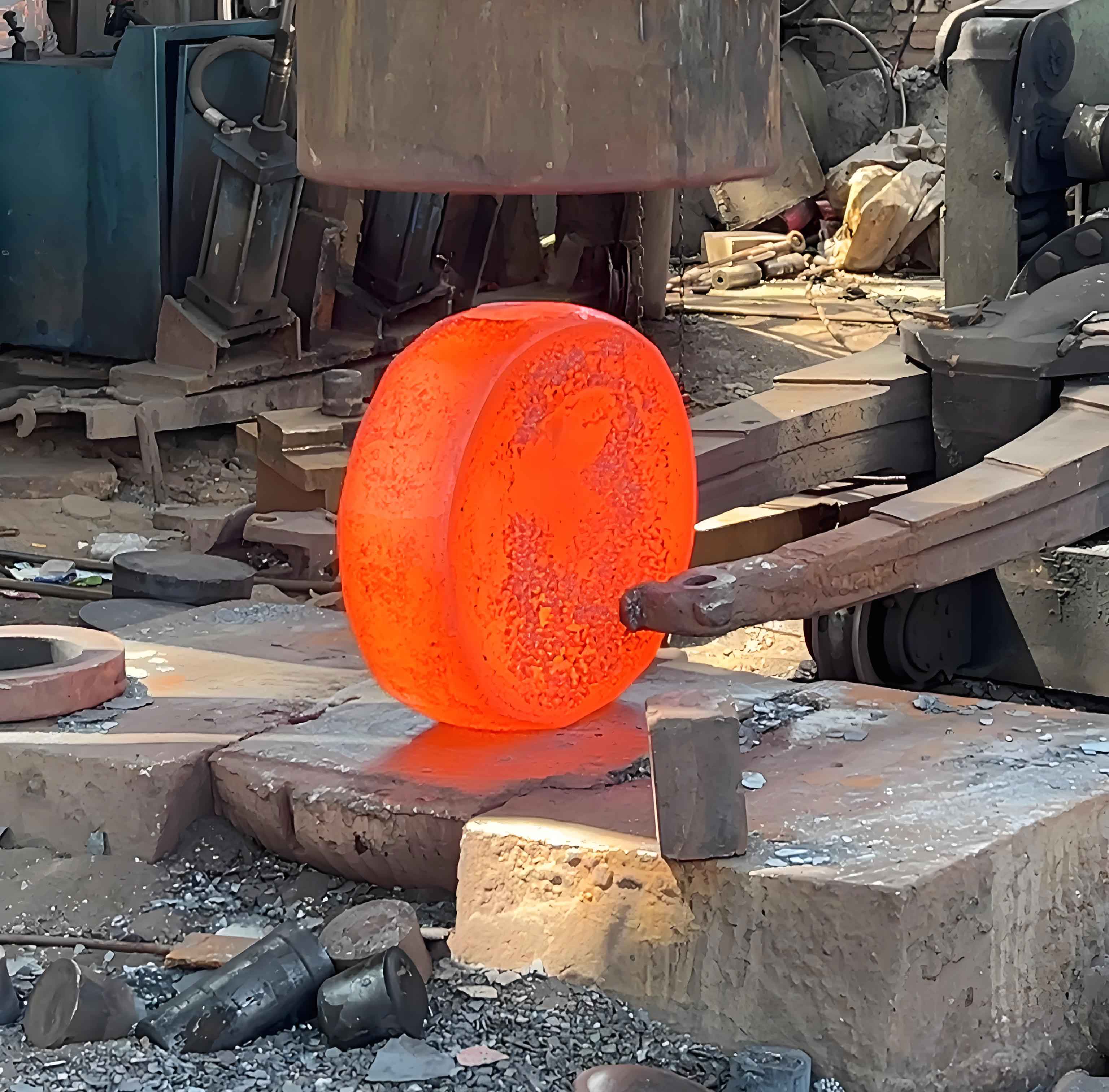
Gear forging represents a transformative approach to manufacturing high-performance transmission components, addressing critical limitations of traditional cutting methods. This study investigates the warm-cold composite forging process for 18CrNiMo7-6 spur gears, combining numerical simulation with virtual reality visualization to optimize precision forming.
1 Introduction
Conventional machining severs metal fiber continuity in gear teeth, inducing stress concentration sensitivity that reduces fatigue strength by approximately 20% and accelerates failure. Precision gear forging maintains continuous metal streamlines along tooth profiles, significantly enhancing mechanical performance. Current research focuses on overcoming key challenges in spur gear forging: excessive forming loads (≥1000 kN for m=5 gears), incomplete corner filling, and severe die wear.
Table 1 compares forging processes, highlighting the advantages of warm-cold composite technology:
| Process | Dimensional Accuracy (Grade) | Surface Roughness (μm) | Economic Batch Size | Die Life (cycles) |
|---|---|---|---|---|
| Hot Forging | 12-16 | >100 | >500 | 2×10³-5×10³ |
| Warm Forging | 9-12 | <30 | >10⁴ | 10⁴-2×10⁴ |
| Cold Forging | 7-11 | ~10 | >3×10³ | 2×10⁴-6×10⁴ |
The warm-cold composite approach synergizes warm forging’s formability (750-850°C) with cold forging’s precision, resolving key limitations:
- Warm stage enables complex geometry formation with 30-40% lower flow stress than cold forging
- Cold finishing achieves surface roughness Ra≤0.8μm and dimensional accuracy IT7
- Residual compressive stresses increase fatigue life by 15-20%
2 Finite Element Theoretical Framework
Accurate simulation requires distinct material models for each forging stage. The governing equations include:
2.1 Rigid-Plastic Finite Element Theory
For warm forging’s large deformations, we apply rigid-plastic formulations with volume constancy:
$$ \nabla \cdot \boldsymbol{\sigma} = 0 $$
$$ \dot{\varepsilon}_{ij} = \frac{1}{2} \left( \frac{\partial v_i}{\partial x_j} + \frac{\partial v_j}{\partial x_i} \right) $$
$$ \sigma = f(\dot{\varepsilon}, \varepsilon, T) $$
The Markov variational principle minimizes functional:
$$ \Pi = \int_V \sigma \dot{\varepsilon} dV – \int_{S_v} P_i v_i dS $$
2.2 Elasto-Plastic Finite Element Theory
Cold finishing simulations incorporate elastic effects via Prandtl-Reuss flow rules:
$$ d\varepsilon_{ij} = d\varepsilon_{ij}^e + d\varepsilon_{ij}^p $$
$$ d\varepsilon_{ij}^e = \frac{1 + \nu}{E} d\sigma_{ij} – \frac{\nu}{E} d\sigma_{kk} \delta_{ij} $$
2.3 Friction and Wear Modeling
Shear friction model governs interface behavior:
$$ \tau_f = \begin{cases}
\mu \sigma_n & \sigma_n < k/\mu \\
k & \sigma_n \geq k/\mu
\end{cases} $$
Archard’s wear model predicts die degradation:
$$ W = K \int \frac{p v}{H} dt $$
3 Precision Forming Process Design
The gear forging process for 18CrNiMo7-6 spur gears (m=5, z=30) follows this sequence:
- Precision blanking
- Induction heating (850±10°C)
- Warm pre-forming
- Piercing
- Annealing
- Surface treatment
- Cold finishing
3.1 Critical Design Parameters
Cold finishing allowance is derived from elastic recovery calculations:
$$ \Delta D_{\text{elastic}} = \frac{D\sigma_s}{2E} \approx 0.19\text{mm} $$
Adopted allowance: 0.2mm (bilateral)
Flash design follows empirical relations:
$$ S = 0.45d – 0.25h + 0.6\sqrt{h} \approx 6.1\text{mm} $$
Thermal expansion compensation for die design:
$$ D_{\text{die}} = D_0 (1 + \alpha_{\text{blank}}\Delta T_{\text{blank}} – \alpha_{\text{die}}\Delta T_{\text{die}}) + \Delta_{\text{finish}} $$
4 Process Simulation and Optimization
Three warm forging approaches were simulated using DEFORM-3D:
4.1 Scheme Comparison
Table 2 summarizes performance metrics for 18CrNiMo7-6 gear forging:
| Scheme | Max Load (kN) | Die Wear (×10⁻⁶mm) | Corner Fill Efficiency |
|---|---|---|---|
| Fixed-die backward extrusion | 1080 | 3.85 | 92% |
| Floating-die unidirectional upsetting-extrusion | 911 | 2.69 | 95% |
| Floating-die bidirectional extrusion | 890 | 2.33 | 98% |
The bidirectional extrusion scheme demonstrated superior metal flow uniformity and 18% lower forming loads than conventional approaches. Optimization with overflow grooves further reduced peak loads:
$$ P_{\text{max}} = 890\text{kN} \xrightarrow{\text{optimization}} 632\text{kN} \quad (\Delta = -29\%) $$
4.2 Parameter Optimization
Orthogonal experiments identified optimal parameters:
| Run | Workpiece Temp (°C) | Die Temp (°C) | Friction Coefficient | Load (kN) | Wear (×10⁻⁶mm) |
|---|---|---|---|---|---|
| 1 | 750 | 200 | 0.10 | 904 | 2.65 |
| 2 | 750 | 250 | 0.20 | 854 | 2.69 |
| 3 | 750 | 300 | 0.25 | 848 | 2.70 |
| 4 | 800 | 200 | 0.20 | 885 | 2.52 |
| 5 | 800 | 250 | 0.25 | 878 | 2.58 |
| 6 | 800 | 300 | 0.10 | 826 | 2.51 |
| 7 | 850 | 200 | 0.25 | 855 | 2.51 |
| 8 | 850 | 250 | 0.10 | 815 | 2.33 |
| 9 | 850 | 300 | 0.20 | 828 | 2.37 |
Optimal combination: 850°C workpiece temperature, 300°C die temperature, μ=0.1
4.3 Cold Finishing Analysis
Finishing allowance significantly affects press loads and die wear:
$$ F_{\text{finish}} = 695\text{kN} \ (0.2\text{mm}) < 1450\text{kN} \ (0.35\text{mm}) $$
The optimal allowance (0.2mm) balances precision requirements with tool life constraints.
5 Virtual Reality Implementation
A data conversion framework bridges DEFORM-3D simulations with Open Inventor visualization:
- Extract STL geometry from DEFORM-3D databases at 10-step intervals
- Convert STL to IV format through topological reconstruction
- Implement kinematic control via SoFieldSensor mechanisms
The transformation algorithm follows:
for each facet in STL:
    extract vertex coordinates V₁, V₂, V₃
    assign vertex index
    write to IV Coordinate3 node
    append indices to IndexedFaceSet
Motion control equations for die components:
$$ z_{\text{upper-die}} = \begin{cases}
v_{\text{press}} \cdot t & t \in [t_1, t_2] \\
z_{\text{final}} & t > t_2
\end{cases} $$

The virtual environment enables real-time interaction with forging parameters, providing insights unobtainable through conventional simulation post-processing.
6 Conclusions and Future Work
The warm-cold composite process demonstrates significant advantages for precision gear forging:
- Bidirectional extrusion reduces forming loads by 29% versus conventional methods
- Optimal parameters: 850°C workpiece, 300°C dies, μ=0.1 with graphite lubricant
- 0.2mm cold finishing allowance minimizes elastic recovery while controlling press loads
- Virtual reality integration enables immersive process validation
Future research directions include experimental validation of residual stress distributions, advanced die life prediction models, and real-time finite element visualization in VR environments. These advancements will further establish gear forging as the manufacturing method of choice for high-performance transmission systems.
