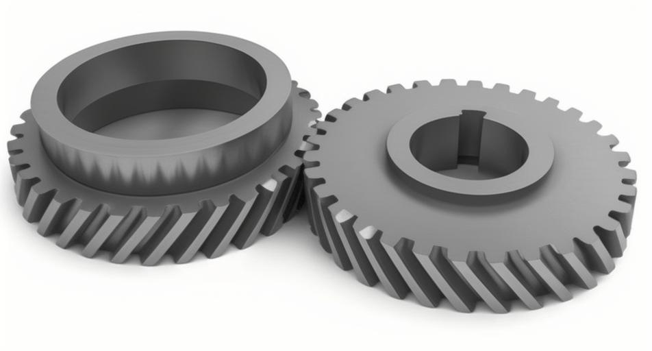
Heavy-duty trucks rely on transmissions with high-performance helical gears to handle increasing power density requirements. This study establishes a systematic approach to determine permissible assembly errors through finite element analysis (FEA), focusing on shaft misalignment and tooth flank clearance.
1. Helical Gear Modeling and Parameters
The helical gear pair for heavy truck transmissions was modeled with the following specifications:
| Parameter | Pinion | Gear |
|---|---|---|
| Number of Teeth | 14 | 35 |
| Module (mm) | 5 | 5 |
| Pressure Angle (°) | 20 | 20 |
| Helix Angle (°) | 15 | 15 |
| Face Width (mm) | 20 | 20 |
The contact stress calculation follows Hertzian contact theory:
$$ \sigma_H = \sqrt{\frac{F}{\pi b} \cdot \frac{(1/\rho_1 + 1/\rho_2)}{(1-\nu_1^2)/E_1 + (1-\nu_2^2)/E_2}} $$
Where \( \rho \) = curvature radius, \( \nu \) = Poisson’s ratio, and \( E \) = Young’s modulus.
2. Static Contact Stress Analysis
2.1 Shaft Misalignment Effects
Simulation results for varying shaft angular misalignments:
| Misalignment (°) | Pinion Stress (GPa) | Gear Stress (GPa) |
|---|---|---|
| 0.2 | 0.71 | 0.68 |
| 0.4 | 0.89 | 0.82 |
| 0.6 | 0.97 | 0.91 |
The stress concentration factor due to misalignment follows:
$$ K_m = 1 + 0.15(\theta/\theta_0)^{1.5} $$
Where \( \theta_0 \) = 0.2° reference angle.
2.2 Tooth Flank Clearance Effects
| Clearance (mm) | Pinion Stress (GPa) | Gear Stress (GPa) |
|---|---|---|
| 0.2 | 0.65 | 0.61 |
| 0.4 | 0.78 | 0.72 |
| 0.6 | 0.94 | 0.88 |
3. Dynamic Response Analysis
The dynamic meshing force considering time-varying stiffness:
$$ F_d(t) = k(t) \cdot \delta(t) + c \cdot \dot{\delta}(t) $$
Where \( k(t) \) = time-varying mesh stiffness, \( \delta(t) \) = transmission error.
3.1 Dynamic Stress Under Misalignment
| Condition | Peak Stress (GPa) | Stress Increase |
|---|---|---|
| 0.2° Static | 0.71 | – |
| 0.2° Dynamic | 0.80 | 12.7% |
| 0.4° Dynamic | 1.10 | 23.6% |
3.2 Dynamic Stress Under Clearance
| Clearance (mm) | Impact Stress (GPa) | Vibration Amplitude |
|---|---|---|
| 0.4 | 0.90 | 0.12 mm |
| 0.6 | 1.20 | 0.18 mm |
4. Assembly Tolerance Recommendations
Based on FEA results for helical gear durability:
| Parameter | Static Limit | Dynamic Limit |
|---|---|---|
| Shaft Misalignment | ≤0.4° | ≤0.2° |
| Flank Clearance | ≤0.6 mm | ≤0.4 mm |
The safety factor equation for helical gear assembly:
$$ S_f = \frac{\sigma_{allow}}{\sigma_{max}} \geq 1.25 $$
This comprehensive analysis demonstrates that dynamic effects significantly reduce permissible assembly errors compared to static conditions. Proper control of helical gear alignment and clearance ensures reliable transmission performance under heavy-load operations.
