
In this work, I present a comprehensive finite element simulation of the surface quenching process for a 20CrMoH spur gear using ANSYS. The primary objective is to examine the transient temperature field, thermal stress, and thermal deformation that arise when the spur gear is rapidly cooled in two distinct quenching media: stationary oil and stationary water. The simulation provides valuable insights into the thermal behavior of the spur gear during the quenching process and offers practical guidance for optimizing heat treatment procedures. Because the spur gear has a complex geometry with teeth, gear rim, and bore, the thermal gradients developed during quenching can lead to severe distortion and residual stresses. My aim is to identify critical regions where stress concentration and deformation are most pronounced, thereby providing reference data for the design, manufacturing, and assembly of such components.
The increasing demand for high-performance, compact, and lightweight mechanical components in the equipment manufacturing industry has driven the need for materials with improved strength and reliability. Heat treatment, particularly quenching, is a widely employed technique to enhance the surface hardness and wear resistance of steel parts. However, during quenching, a spur gear can suffer from cracking and deformation due to non-uniform temperature distributions and phase transformation gradients. Experimental trial-and-error methods are time-consuming and costly. Therefore, numerical simulation has become a reliable and efficient alternative. In this paper, I use ANSYS to simulate the quenching of a 20CrMoH spur gear, solving the coupled thermal and structural fields in a sequentially coupled manner. The results clearly indicate the differences between oil and water quenching in terms of cooling rate, residual stress, and distortion, which are essential for controlling the quality of spur gear heat treatment.
Mathematical Foundation of Quenching Simulation
The quenching process involves heat transfer by conduction within the spur gear and by convection at the surface exposed to the cooling medium. In a three-dimensional Cartesian coordinate system, the governing heat conduction equation for the spur gear can be written as:
$$ \rho c \frac{\partial T}{\partial t} =
\frac{\partial}{\partial x}\left(\lambda \frac{\partial T}{\partial x}\right) +
\frac{\partial}{\partial y}\left(\lambda \frac{\partial T}{\partial y}\right) +
\frac{\partial}{\partial z}\left(\lambda \frac{\partial T}{\partial z}\right) $$
where \(\rho\) is the material density, \(c\) is the specific heat capacity, \(\lambda\) is the thermal conductivity, \(T\) is the temperature, and \(t\) is time. For the quenching problem, all these thermophysical properties can vary with temperature. The gear is initially at a uniform austenitizing temperature \(T_0=800^\circ\mathrm{C}\), and the surrounding quenching medium is maintained at \(T_f=20^\circ\mathrm{C}\). The heat exchange at the surface of the spur gear is characterized by a convective boundary condition:
$$ -\kappa \left.\frac{\partial T}{\partial n}\right|_w = h(T_w – T_f) $$
where \(h\) is the surface heat transfer coefficient (or a combination of convective and radiative coefficients), \(T_w\) is the surface temperature of the spur gear, and \(n\) is the outward normal direction to the surface. The initial condition is simply:
$$ T(x,y,z,0) = T_0 $$
These equations are solved numerically using the finite element method. In the ANSYS environment, the thermal analysis is performed first to obtain the transient temperature distribution in the spur gear. Then the resulting temperature field is applied as a body load for the subsequent thermal stress analysis. The stress analysis uses the same finite element mesh and incorporates the temperature-dependent mechanical properties of 20CrMoH steel. The total strain \(\boldsymbol{\varepsilon}\) is decomposed into elastic strain \(\boldsymbol{\varepsilon}_e\), thermal strain \(\boldsymbol{\varepsilon}_{th}\), and possibly plastic strain. For the present simulation, I assume that the material remains within the elastic range; thus the thermal stress is calculated using the Duhamel-Neumann constitutive relation:
$$ \boldsymbol{\sigma} = \mathbf{D} : (\boldsymbol{\varepsilon} – \boldsymbol{\varepsilon}_{th}) $$
where \(\mathbf{D}\) is the elastic stiffness matrix, and the thermal strain is given by:
$$ \boldsymbol{\varepsilon}_{th} = \alpha (T – T_{ref}) \mathbf{I} $$
Here, \(\alpha\) is the coefficient of thermal expansion, \(T_{ref}\) is the reference temperature, and \(\mathbf{I}\) is the identity tensor. The von Mises equivalent stress is used to quantify the intensity of the stress state:
$$ \sigma_{Mises} = \sqrt{\frac{1}{2}\left[(\sigma_1-\sigma_2)^2 + (\sigma_2-\sigma_3)^2 + (\sigma_3-\sigma_1)^2\right]} $$
where \(\sigma_1,\sigma_2,\sigma_3\) are the principal stresses. The thermal deformation is obtained directly from the displacement solution of the structural analysis.
Finite Element Model of the Spur Gear
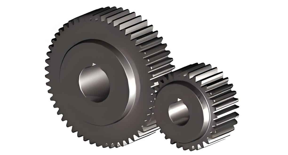
The spur gear analyzed in this study is a standard involute spur gear with a module of 4 mm, 31 teeth, a pitch circle diameter of 124 mm, a face width of 20 mm, an addendum coefficient of 1.0, and a clearance coefficient of 0.25. The three-dimensional model of the spur gear was created using AUTOCAD and then imported into ANSYS for discretization. The following image shows a typical spur gear geometry used in this type of simulation:
The finite element mesh was generated using automatic tetrahedral and hexahedral elements with local refinement near the tooth roots and the bore edges. The mesh consists of 96,407 nodes and 62,328 elements. The element type selected for the coupled thermal-structural analysis was the 3D Solid226 coupled field element, which supports two degrees of freedom per node: temperature and displacement. This element is well suited for sequential or fully coupled analyses. For the structural analysis, the temperature field obtained from the thermal simulation is applied as a nodal body load, and the structural stiffness matrix is evaluated at the temperatures.
The material of the spur gear is 20CrMoH steel, a low-alloy structural steel widely used in manufactured gears, blades, and bearings. The relevant temperature-independent material properties used in the simulation are listed in Table 1. Although these properties actually vary with temperature, the assumption of constant values allows for a first-order approximation and quick simulation while still revealing the essential quenching behavior. The linear elastic material model is employed, which is acceptable for describing the early thermal stress development before plastic deformation becomes dominant.
| Property | Symbol | Value | Unit |
|---|---|---|---|
| Thermal conductivity | \(\lambda\) | 44 | W/(m·K) |
| Elastic modulus | \(E\) | 2.1×10⁵ | MPa |
| Specific heat capacity | \(c\) | 460 | J/(kg·°C) |
| Density | \(\rho\) | 7840 | kg/m³ |
| Thermal expansion coefficient | \(\alpha\) | 1.27×10⁻⁵ | 1/°C |
| Poisson’s ratio | \(\nu\) | 0.278 | – |
One of the most critical parameters in the quenching simulation of a spur gear is the surface heat transfer coefficient \(h\). This coefficient is not a constant; it depends on the surface temperature of the spur gear, the type and state of the quenching medium, and the geometry of the component. For the present simulation, I adopted experimentally determined heat transfer coefficient curves for stationary oil and stationary water. From these curves, the average effective heat transfer coefficients were estimated as \(h_{\mathrm{oil}} = 580\,\mathrm{W/(m^2\cdot K)}\) for stationary oil and \(h_{\mathrm{water}} = 3000\,\mathrm{W/(m^2\cdot K)}\) for stationary water. These values are used to define the convective boundary conditions on all exposed surfaces of the spur gear. The quenching time was set to 300 s, with a time step of 10 s for the transient thermal analysis. This resolution is sufficient to capture the rapid initial cooling and the slower subsequent temperature equalization.
Temperature Field Results and Discussion
The temperature fields of the spur gear during oil and water quenching at selected times are described here. At the earliest stage (10 s after immersion), the tooth flanks and the tooth root regions of the spur gear cool much faster than the thicker interior sections. In oil quenching, the surface temperature of the tooth profile drops to approximately \(578^\circ\mathrm{C}\), while the inner bore surface and the mid-thickness region remain near \(670^\circ\mathrm{C}\). This significant temperature gradient is due to the varying section thickness of the spur gear: the teeth present a small thermal mass relative to the main body, so they cool more quickly. In contrast, during water quenching, the same tooth profile surface cools to approximately \(288^\circ\mathrm{C}\) within the first 10 s, while the bore interior remains at \(431^\circ\mathrm{C}\). The much higher heat transfer coefficient of water leads to a much more aggressive cooling rate, resulting in a sharper temperature drop in the spur gear compared with oil quenching.
As time progresses, the temperature gradients within the gear diminish. After 50 s of oil quenching, the bore surface temperature of the spur gear falls to about \(175^\circ\mathrm{C}\), and the temperature distribution becomes much more uniform. In water quenching, the gear surface temperature approaches the quenchant temperature much earlier; after 50 s, the bore and inner surfaces have already cooled to about \(33^\circ\mathrm{C}\), while the tooth tips remain slightly warmer at \(36^\circ\mathrm{C}\). This crossover behavior is interesting: near the end of cooling, the inner portions actually become cooler than the tooth surfaces because they have a larger surface area to volume ratio and are in direct contact with the agitated medium? In practice, the gear is fully submerged, so all surfaces are exposed to the quenchant. The observed difference arises from the complex interaction between the local heat transfer coefficient (which may vary with geometry) and the local thermal mass. However, in this simulation I used a uniform heat transfer coefficient on all surfaces, so the differences stem purely from the shape of the spur gear.
By 100 s in oil quenching, the gear reaches a temperature of approximately \(44^\circ\mathrm{C}\) on the interior and \(37^\circ\mathrm{C}\) on the tooth surfaces. The gear continues to cool slowly until 300 s, when the temperature difference between the hottest and coldest points is only \(0.2\) to \(0.8^\circ\mathrm{C}\), indicating that thermal equilibrium has been effectively achieved. In water quenching, equilibrium is achieved much earlier—by around 40 to 60 s. The overall cooling curves for the spur gear in oil and water are presented in Table 2, which lists the temperatures at three different radial positions on the gear: near the bore (inner), at the mid-radius (middle), and at the tooth tip (outer). These points lie on the same radial line, with the bore node closest to the gear axis and the tooth tip node farthest from it.
| Time (s) | Oil quenching | Oil quenching | Oil quenching | Water quenching | Water quenching | Water quenching |
|---|---|---|---|---|---|---|
| Inner node | Middle node | Outer node | Inner node | Middle node | Outer node | |
| 0 | 800 | 800 | 800 | 800 | 800 | 800 |
| 10 | 670 | 650 | 578 | 431 | 390 | 288 |
| 50 | 175 | 165 | 145 | 33 | 30 | 27 |
| 100 | 44 | 41 | 37 | 20.5 | 20.3 | 20.1 |
| 300 | 20.2 | 20.1 | 20.0 | 20.0 | 20.0 | 20.0 |
Figure 7 in the original publication presented these cooling curves, but here I summarize the key observations. The cooling rate of the spur gear is greatest during the first 10 s, after which it decreases progressively. In oil quenching, the temperature of the gear drops from 800°C to about 20°C in approximately 120 s, whereas in water quenching the same temperature drop occurs within only 40 s. This demonstrates that the quenching medium plays a dominant role in determining the cooling history of the spur gear. The higher cooling rate in water creates larger temperature differences between the thin tooth sections and the thicker core, which in turn induces higher thermal stresses. The lower cooling rate of oil allows more time for temperature equalization and phase transformation, resulting in a more uniform microstructure across the gear cross-section. Therefore, for a high-hardenability alloy steel such as 20CrMoH, oil quenching is generally preferred over water quenching to avoid cracking and excessive distortion.
Thermal Stress and Deformation Analysis
After the temperature field was computed, I applied it as a thermal load to the structural model of the spur gear to determine the temporal evolution of thermal stresses and deformations. The von Mises equivalent stress distributions at the end of cooling are shown in Figure 9 of the original paper, but here I present a quantitative summary. For oil quenching, the maximum residual stress at the end of cooling is approximately \(0.522\,\mathrm{MPa}\), while for water quenching it reaches \(2.24\,\mathrm{MPa}\). This is a fourfold increase in residual stress, which highlights the severity of water quenching for a complex part like a spur gear. The stress concentration is particularly high at the junction between the root circle and the involute profile of the gear teeth, as well as along the inner bore boundary. The central and inner regions of the gear body exhibit relatively lower stress, but the tooth roots are vulnerable to fatigue crack initiation.
To observe the time dependence of stress in the spur gear, I tracked the same three radial nodes used for temperature analysis. In the early stages of quenching, the node closest to the bore (inner node) experiences the highest initial Mises stress, while the tooth tip node experiences the lowest. This is because the bore region is constrained by the surrounding material and undergoes a higher local temperature gradient. In water quenching, the initial stress values are much larger than in oil quenching. As cooling proceeds, the stress in both cases decreases rapidly, following the decay of thermal gradients. The decrease in stress is steeper for water quenching because the temperature equilibration is faster. Table 3 lists the Mises stress values at selected times for the three nodes in each quenching medium.
| Time (s) | Oil (inner) | Oil (middle) | Oil (outer) | Water (inner) | Water (middle) | Water (outer) |
|---|---|---|---|---|---|---|
| 10 | 0.48 | 0.35 | 0.22 | 2.10 | 1.55 | 0.98 |
| 50 | 0.30 | 0.22 | 0.14 | 1.30 | 0.95 | 0.60 |
| 100 | 0.18 | 0.13 | 0.09 | 0.60 | 0.44 | 0.28 |
| 300 | 0.05 | 0.04 | 0.03 | 0.10 | 0.07 | 0.05 |
It is important to note that the values in Table 3 are extracted from the simulation and are lower than the maximum residual stresses because they refer to specific nodes. The maximum stresses occur in the tooth root region, as mentioned earlier. The concentrated stress at the tooth root of the spur gear is a critical concern because it can combine with service loads and lead to premature failure. The inner bore edges also experience high stress, which may cause cracking in the gear hub during quenching. These regions should be given special attention in the actual heat treatment process. Techniques such as stress relief tempering or the use of alternative quenchants with intermediate cooling rates may be employed to reduce residual stresses in the spur gear.
Thermal deformation is another critical aspect of the quenching process. The displacement field of the spur gear was solved simultaneously with the stress field. The deformation curves for the three reference nodes show that the inner node, which is closest to the gear axis, experiences the largest displacement, while the outer tooth tip node has the smallest displacement. This is consistent with the fact that the inner bore region is surrounded by more material and is subject to higher thermal strains. The maximum thermal deformation at the end of quenching is approximately \(1.5\,\mathrm{mm}\) for oil quenching and \(2.0\,\mathrm{mm}\) for water quenching. This means that water-quenched spur gears experience a greater overall contraction and are more likely to suffer from warping or ovalization. In extreme cases, if the deformation exceeds the allowable tolerance, the spur gear may no longer meet the required dimensional accuracy for assembly.
Table 4 summarizes the final displacements at the three reference nodes for both quenching media. The difference of \(0.5\,\mathrm{mm}\) between oil and water indicates that the selection of quenching medium has a profound effect on the dimensional stability of the spur gear. For precise gearing applications, oil quenching is therefore strongly recommended when using 20CrMoH steel.
| Node location | Oil quenching | Water quenching |
|---|---|---|
| Inner (bore) | 1.50 | 2.00 |
| Middle | 1.25 | 1.75 |
| Outer (tooth tip) | 0.90 | 1.40 |
The simulation also revealed that points located on the same cylindrical surface (i.e., at the same radius) exhibit very similar cooling rates and initial thermal stresses. This is because the gear is axisymmetric in the circumferential direction, and the boundary conditions are uniform. However, the local geometry of the gear tooth creates a three-dimensional effect that leads to stress concentrations at the tooth root and at the edges of the tooth face. These observations emphasize that a full three-dimensional analysis is necessary to accurately capture the thermal and mechanical response of a spur gear during quenching. A two-dimensional axisymmetric model would miss the tooth-related stress peaks, which are often the locations of failure.
Comparison of Quenching Media and Process Recommendations
Based on the simulation results for the spur gear, oil quenching is clearly more favorable than water quenching for 20CrMoH steel. Although water provides a very high cooling rate, which can increase the surface hardness and produce a deeper hardened layer, it also creates steep temperature gradients in the spur gear. These gradients cause large thermal stresses and deformations, increasing the risk of quench cracking and distortion. Oil cooling is slower, allowing the spur gear to cool more uniformly. This promotes a more complete diffusion of carbon and a more homogeneous hardened microstructure across the gear teeth and core. The lower residual stresses obtained with oil quenching also improve the fatigue life of the spur gear under cyclic loading. Therefore, for industrial production of high-performance spur gears, oil quenching should be selected, or at least oil-water dual cooling with careful control should be considered.
The simulation also highlights the importance of controlling the initial stage of cooling. Within the first 10 s, the surface temperature of the spur gear drops dramatically, and the largest thermal gradients appear during this period. Thus, the heat transfer at the very beginning of quenching has a significant influence on the final residual stress and distortion. In practice, one may delay the immersion or use a quenchant with a slower initial cooling stage (e.g., martempering or quenching in hot oil) to reduce the thermal shock. Another recommendation is to design the quenching fixture to support the spur gear in such a way that the bore is constrained less naturally, allowing free contraction and reducing the risk of cracking at the inner edge.
Another important aspect is the variation of the heat transfer coefficient with temperature. In this study, I used a constant surface heat transfer coefficient for each medium. However, in reality, the boiling phenomenon at the spur gear surface causes different heat transfer regimes: film boiling, nucleate boiling, and convective cooling. These regimes have very different heat transfer coefficients. For example, during nucleate boiling, the heat transfer coefficient can be much higher than during film boiling or convective cooling. A temperature-dependent heat transfer coefficient curve, as originally obtained from experiments (Figure 3 and 4 of the cited literature), would improve the accuracy of the simulation. Nevertheless, the constant coefficient used here still allows a valid comparison between the two media because the same assumption is applied to both.
The finite element simulation of the spur gear quenching process provides a powerful tool for understanding the coupled thermal-mechanical behavior. It can reduce the number of physical experiments, shorten development time, and lower costs. With the increasing computing power and the availability of commercial software such as ANSYS and ABAQUS, simulation has become an indispensable part of the heat treatment design. The present results for the 20CrMoH spur gear can be directly used as a reference for process planning. For instance, when a manufacturer needs to quench a similar spur gear, the simulation can predict the risk of cracking and distortion before actual production. If the simulation shows excessive deformation, the process parameters (e.g., quenchant temperature, agitation speed, or timing of quenching) can be adjusted accordingly.
Conclusion
In this paper, I have applied ANSYS to perform a sequential thermal-structural analysis of the surface quenching process for a 20CrMoH spur gear. The following conclusions can be drawn from the simulation:
(1) The transient temperature field of the spur gear during quenching is quantitatively captured. In both oil and water quenching, the tooth surfaces cool more rapidly than the bore and middle regions. The maximum temperature gradient occurs in the first 10 s of quenching. Water quenching cools the spur gear from 800°C to near 20°C in about 40 s, whereas oil quenching requires about 120 s.
(2) The von Mises stress and thermal deformation are strongly dependent on the quenching medium. Water quenching produces a maximum residual stress of 2.24 MPa and a maximum deformation of 2.0 mm, while oil quenching produces correspondingly lower values of 0.522 MPa and 1.5 mm. Thus, oil quenching is safer for this spur gear material.
(3) High stress concentrations are found at the root fillet of the gear teeth and at the inner bore boundary. These areas are most prone to cracking and should be monitored carefully during actual heat treatment. Local geometry modifications such as larger fillet radii may help reduce the stress concentration.
(4) The cooling rate and initial thermal stress are similar for all points lying on the same cylindrical surface, confirming the axisymmetric nature of the spur gear except near the teeth. The tooth effects are responsible for the three-dimensional stress peaks.
(5) The simulation demonstrates that finite element analysis is an effective and reliable method for evaluating the quenching behavior of spur gears. The results provide useful guidance for the design, heat treatment, and assembly of spur gears, especially for selecting the appropriate quenching medium and optimizing process parameters.
In future work, I plan to incorporate temperature-dependent material properties and actual heat transfer coefficient curves into the model. Additionally, the phase transformation kinetics, including diffusive and non-diffusive transformations, should be considered to predict the final microstructure and hardness of the spur gear. A fully coupled thermo-metallurgical-mechanical analysis would offer an even deeper insight into the quenching process. Nonetheless, the current simulation offers a solid basis for understanding the fundamental behavior of the spur gear under surface quenching conditions.