Use Solidworks software to conduct 3D solid modeling for the rotating pair of double circular arc helical gear pump. The material of the rotor structure of the gear pump model is shown in Table 1 below.
| Grade | Elastic modulus MPa | Poisson’s ratio γ | Density kg/m3 | Yield strength MPa |
| 30CrMnTi | 2.07E+05 | 0.25 | 7800 | 1050 |
1. Fluid grid division
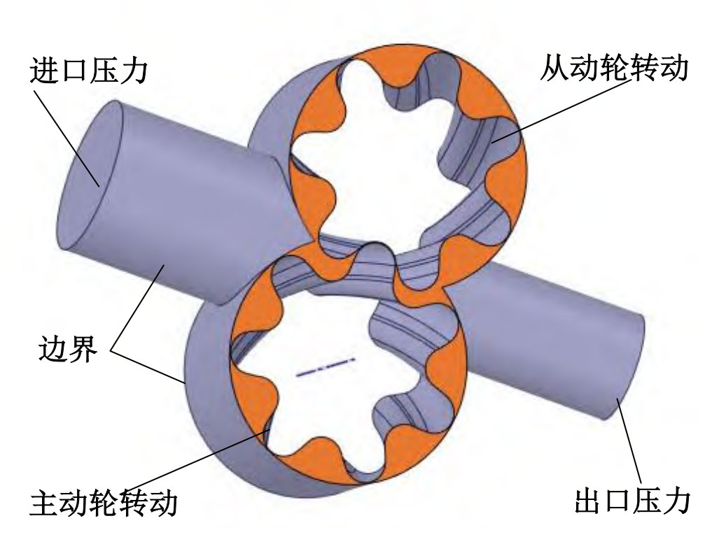
Using ANSYS Space Claim software to build a gear pump basin, due to the possibility of losing the 3D model of the rotating pair of the double arc helical gear pump during data transmission, the software’s built-in one click repair function ensures the integrity of the rotor model of the double arc helical gear pump. Use the software to set the boundary conditions for extracting the watershed, dividing the entire watershed into four parts: boundary, inlet pressure, outlet pressure, and master slave wheel. The boundary conditions are shown in Figure 1.
2. Flow field calculation model
Considering that the gap formed between the tooth top and the pump body has a significant impact on the flow field, in order to improve the quality of the grid inside the gap and ensure the accuracy and convergence of watershed calculations, densification is adopted at the thinner gap position to increase the number of cell layers. The encryption method at the thin-walled position is patch independent. Compared to hexahedral mesh division, with the same accuracy, tetrahedral mesh units and nodes will be more. When using tetrahedral mesh division, the accuracy of mesh division is controlled by setting size control and boundary conditions (Proximity). After grid division, the watershed nodes are approximately 222. 70000, with a total number of units of approximately 11.3 million. Areas with substandard grid quality will be treated to ensure that the processed grid quality meets the Fluent computing requirements.
| Name | X | Y | Z |
| Driving gear | 0.5546169 | -0.03010371 | -0.2883893 |
| Driven gear | 0.03457587 | -0.03012145 | -0.2883893 |
Using Fluent software for full flow field numerical analysis, for double arc helical gear pumps, the hydraulic oil should be considered as a viscous incompressible unsteady flow (Transient). Set the absolute speed as the solver speed, using the default standard wall functions. The calculation method uses implicit solving algorithm (Implicit) and first-order upwind format, while using hybrid initialization. The position of the mass center of the driving and driven gears is shown in Table 2.
3. Flow field calculation results
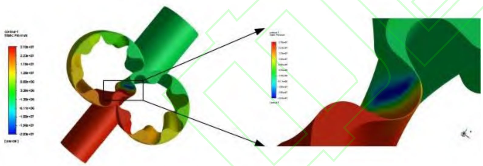
As shown in Figure 2, the pressure distribution of the double arc helical gear pump is 1 atmospheric pressure tooth at the inlet, 25 MPa at the outlet, and 10000 r/min for the driving and driven wheels. The convergence accuracy of the calculation is 10-3. As shown in Figure 3, the liquid pressure is the lowest at the inlet edge and reaches its maximum near the outlet of the rotor. Along the direction of liquid flow, the liquid pressure gradually increases. There are multiple relatively closed volumes between the inner wall of the pump body and the surface of the rotor. The pressure value within the volume is relatively stable, and the pressure value in the transition zone from the high-pressure zone to the low-pressure zone decreases linearly.
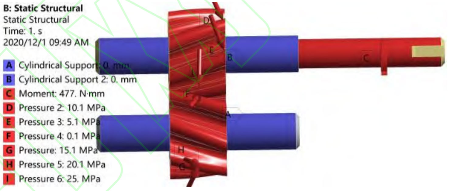
From Figure 3, it can be seen that there is maximum pressure and minimum negative pressure at the meshing position of the double arc helical gear pump rotor, minimum negative pressure at the meshing position of the inlet rotor, and maximum pressure at the meshing position of the outlet rotor. Using numerical calculation methods to analyze the surface pressure of the rotor and derive the pressure distribution load of the flow field through real-time data transmission.