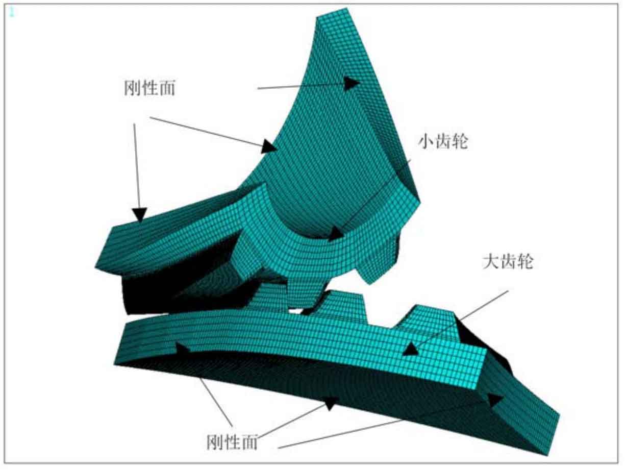
The finite element method is still used to analyze the force of bevel gear model. The grid size setting, physical parameters, boundary conditions and their application methods are basically consistent with the finite element analysis of the model in Chapter 3. For the bevel gear entity, the low-order hexahedron element solid185 element is selected to divide the large and small parts of the grid. Near the contact area, the side length of some units participating in the contact tooth surface is set to 0.2mm, and the side length of other units is set to 1-2mm. The application of rotation is completed by introducing kinematic unit and MPC 184 unit. The final mesh model is shown in Figure 1. The physical parameter Young’s modulus is 2.05 × 10⁵Mpa, Poisson’s ratio is 0.3. For the boundary load, set the output load to 540nm. Finally, apply 180nm input torque on the bevel gear small wheel and 0.3rad/s speed on the bevel gear big wheel.
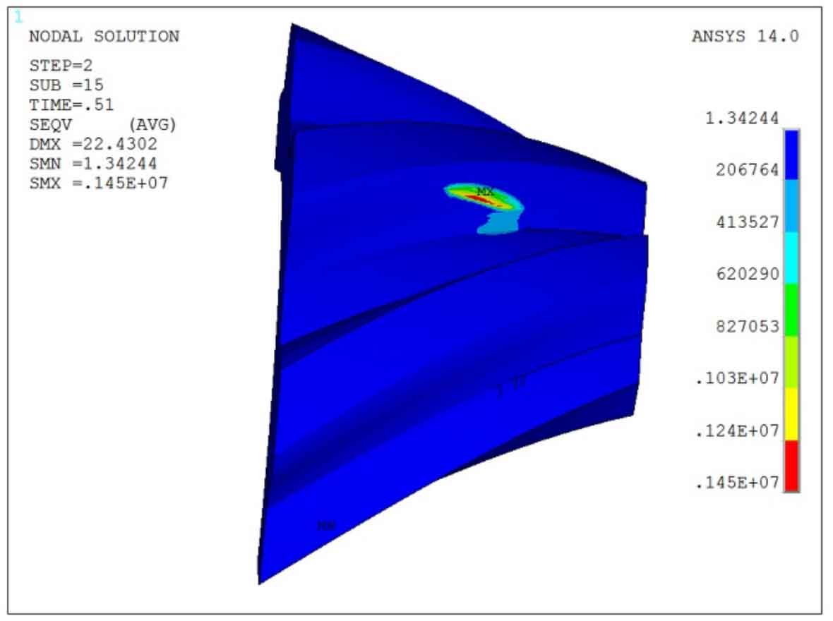
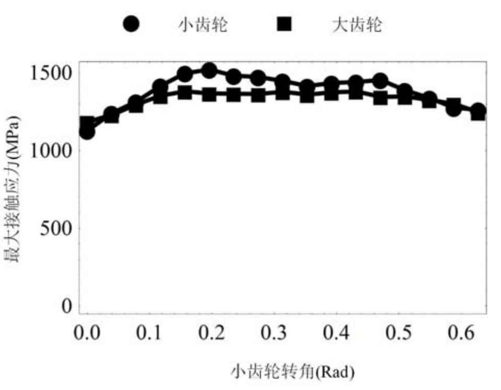
After solving the finite element model, the force distribution of bevel gear small wheel and large wheel in power transmission is obtained. Figure 2 shows the bending and contact stress of the bevel gear pinion when the contact point is located in the middle of the tooth surface. Here, due to the joint action of tooth surface contact deformation and tooth bending deformation, the contact area is still approximately elliptical. Fig. 3 shows the change of the maximum contact stress of a single tooth in a meshing cycle. It can be seen that the maximum contact stress is within 1450mpa. Since only a single tooth is loaded in the middle of the tooth surface, the time when the maximum contact stress appears on the tooth surface is in the middle of the tooth surface. On both sides along the tooth width direction, the contact stress is relatively reduced because two teeth share the load together.
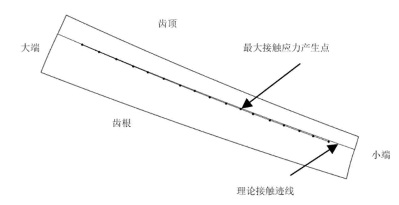
In order to analyze the deviation between the theoretical design and the actual situation, the maximum force point in the finite element analysis of bevel gear is still set as the qualitative contact point, that is, in the actual meshing process, it is considered that the bevel gear pair contacts at this point. Figure 4 shows the deviation between the theoretical contact trajectory and the qualitative contact point. Here, the maximum deviation between the theoretical contact point and the qualitative contact point is 0.15mm. The theoretical prediction is basically consistent with the results of finite element analysis.