
I treat the production of automotive rear-axle bevel gear forged gear blanks as a coupled mechanical, hydraulic, and metrological problem rather than as a single forming operation. The forged gear blanks must survive a severe service environment, carry heavy load, resist wear, and remain safe in operation. They are also common replacement parts during major vehicle overhaul, so their dimensional consistency has direct consequences for material consumption, machining allowance, assembly behavior, and field reliability. My approach in this article is to combine two improvements that I have found especially effective: a hydraulic-motor-driven handling and feeding arrangement with a double-row sprocket for impact resistance, and an on-line dimensional control method for the ring-rolling process that produces forged gear blanks with an outer-diameter tolerance of about \(\Delta \phi \pm 1\,\mathrm{mm}\).
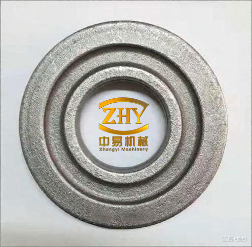
The central object is the forged gear blank, not the finished gear. A forged gear blank that is too thick wastes material and machining time; one that is too thin risks insufficient stock, unstable heat treatment, or unacceptable tooth-root properties. A forged gear blank with an oversized outer diameter increases machining allowance; one with an undersized outer diameter may fail to clean up during finishing. Therefore I define the control problem around the geometry of the forged gear blank at the end of stable rolling and during the finishing stage. I use volume invariance as the physical basis, outer diameter as the control criterion, and a simplified first-order calibration for the programmable controller that executes the sequence.
The service-driven reason for tighter control of forged gear blanks. The rear-axle bevel gear operates under shock, fatigue, and high contact stress. The forged gear blank is the precursor of that component, so its mass distribution and section thickness influence subsequent forging, heat treatment, and machining. In my production experience, the most practical way to improve the forged gear blank is to control the ring-rolling stage with a repeatable model and a robust drive. A hydraulic motor on the uncoiler or manipulator gives smooth torque delivery and overload protection, while the rolling model gives a predictable stopping point. These two measures support each other: the drive stabilizes the motion, and the control model stabilizes the dimension.
I summarize the main process requirements for forged gear blanks in the following table. The values are the acceptance targets and sampling conditions that I use for the model and for the control sequence.
| Process item | Symbol or index | Role in forged gear blanks | Target or condition | Consequence of poor control |
|---|---|---|---|---|
| Finished outer diameter | \(D_e\) | Final size criterion of the forged gear blank | Within the drawing tolerance | Machining stock error or incomplete cleanup |
| Outer-diameter accuracy | \(\Delta \phi\) | Measured production capability | About \(\pm 1\,\mathrm{mm}\) | Scrap, rework, or unstable machining |
| Thickness at stable rolling | \(b\) | State variable of the forged gear blank | Sampled at \(b_0\) | Wrong volume estimate |
| Sampling thickness | \(b_0\) | Point at which the cavity is full | Example \(72\,\mathrm{mm}\) | Incomplete geometry in the model |
| Maximum transition thickness | \(b_{e’}\) | End of stable rolling | About \(67\,\mathrm{mm}\) in the example | Late or early transition to finishing |
| Stable-rolling window | \(t_s\) | Time available for sampling and calculation | Less than \(0.5\,\mathrm{s}\) | Missed control action |
| Main feed speed | \(v\) | Motion input for the rolling model | Constant in the feed stage | Model mismatch and position error |
| Roll surface speed | \(v_1\) | Reference speed of the rolling pass | Determined by the machine setting | Incorrect geometric ratio |
The first kinematic relation I use is the ratio between the feed speed and the roll-surface speed. For the stable rolling stage of forged gear blanks, I write
$$g=\frac{v}{v_1}.$$
Here \(v\) is the feed speed during the stable rolling stage and \(v_1\) is the surface speed of the main rolling wheel. The parameter \(g\) is not an arbitrary tuning factor; it links the axial motion of the main slide with the radial deformation of the ring. Once the machine settings and the tooling for a family of forged gear blanks are fixed, \(g\) becomes a known model input. I use it to keep the volume equation consistent with the actual motion of the machine.
For the ring-rolling geometry, I describe the instantaneous volume of the forged gear blank as a quadratic function of the outer diameter. This is the core of my on-line model:
$$V=C_2D^2+C_1D+C_0.$$
In this expression, \(D\) is the current outer diameter and \(V\) is the instantaneous volume of the ring. The coefficients \(C_2\), \(C_1\), and \(C_0\) collect the section shape, the inner and outer step dimensions, the groove height, the taper angles, and the feed ratio. I calculate these coefficients once for each part family and store them in the controller. For a given forged gear blank drawing, the geometry of the closed groove and the main roll is fixed, so the polynomial is valid for every blank in that family, provided that the cavity has been filled before sampling.
Volume invariance as the basis for controlling forged gear blanks. At a suitably chosen moment during stable rolling, I sample the outer diameter \(D_0\) and the thickness \(b_0\). The cavity must already be full at this moment. If the cavity is not full, the measured volume does not represent the forged gear blank, and the control model loses its physical meaning. I therefore choose \(b_0\) from two competing requirements: it should be as small as possible for accurate volume calculation, but it must leave enough time for sampling, calculation, decision-making, and actuation before the thickness reaches \(b_{e’}\).
From the measured state, I compute the reference volume:
$$V_0=V(b_0,D_0).$$
Because the volume of the forged gear blank is conserved during plastic deformation, I require
$$V_0=V.$$
After the stable rolling stage, the outer diameter must be controlled within the tolerance of the finished forged gear blank. Let the target outer diameter at the end of stable rolling be \(D_e\). At that diameter, the corresponding thickness is \(b_{e’}\). Solving the volume equation gives the transition thickness:
$$b_{e’}=\frac{-A_1+\sqrt{A_1^2-4A_2A_0}}{2A_2}.$$
The coefficients \(A_2\), \(A_1\), and \(A_0\) are functions of the groove height, the step diameters, the taper angles, the target outer diameter, and the sampled volume. I do not expose these coefficients to the operator. Instead, I keep them in the model library for each forged gear blank family. The table below shows how I assign the model coefficients and when they must be recalculated.
| Coefficient group | Physical information contained | Use in the controller | Recalculation trigger |
|---|---|---|---|
| \(A_2\) | Groove height and section geometry | Quadratic term for \(b_{e’}\) | Tooling change or height change |
| \(A_1\) | Target diameter, step diameters, taper angles | Linear term for \(b_{e’}\) | Forged gear blank drawing change |
| \(A_0\) | Sampled volume and lower-section geometry | Constant term for \(b_{e’}\) | Material or blank-weight change |
| \(B_2\) | Rolling ratio and groove height | Quadratic term for \(D_J\) | Feed speed or roll speed change |
| \(B_1\) | Thickness at transition and taper geometry | Linear term for \(D_J\) | Transition thickness change |
| \(B_0\) | Volume and lower-section constants | Constant term for \(D_J\) | Blank-weight or groove change |
The transition thickness \(b_{e’}\) tells me when stable rolling should end, but it is not the best variable for direct control of forged gear blanks. The reason is practical and important: the outer diameter of the ring grows much faster than the wall thickness decreases. If I control the endpoint by wall thickness, a small system delay causes a large outer-diameter error. For that reason, I use the outer diameter as the control criterion. I substitute the transition thickness into the volume equation and solve for the outer diameter at which the machine must leave the stable rolling stage:
$$D_J=\frac{-B_1+\sqrt{B_1^2-4B_2B_0}}{2B_2}.$$
The quantity \(D_J\) is the decision diameter for forged gear blanks. When the measured outer diameter reaches \(D_J\), the stable rolling stage ends and the finishing stage begins. The finishing stage is necessary because the inner contour of the forged gear blank may still contain a spiral or otherwise non-circular trace that must be rounded out. After the finishing stage, the outer diameter reaches the final target \(D_e\), or the part has been rolled through one complete revolution, and the process stops. I summarize this sequence below.
| Stage | Condition | Action | Purpose for forged gear blanks | Risk if skipped | |
|---|---|---|---|---|---|
| Cavity filling | Before \(b_0\) | Maintain stable feed | Establish full section for volume measurement | Incorrect volume and wrong decision diameter | |
| Sampling | \(b=b_0\) | Read \(D_0\) and \(b_0\) | Fix the reference volume of the forged gear blank | Model drift from blank-weight variation | |
| Calculation | Immediately after sampling | Evaluate \(D_J\) | Predict the end of stable rolling | Late transition and outer-diameter overshoot | |
| Stable rolling | \(D<d_j\) | Continue main feed | Complete the main deformation of the forged gear blank | Incomplete section or excessive finishing stock | |
| Transition | \(D\ge D_J\) | Stop main feed | Enter finishing with controlled diameter | Outer-diameter error beyond tolerance | |
| Finishing | Until \(D\ge D_e\) or one revolution | Round out the inner contour | Stabilize the final geometry of the forged gear blank | Residual spiral trace or non-circularity | |
| Retraction | After finishing | Fast return of the main roll | Release the forged gear blank | Lost cycle time or marking |
Why I simplify the model for on-line control of forged gear blanks. The equations above are mathematically correct, but they are not convenient for a compact programmable controller. The controller on the rolling machine does not have a square-root instruction, and the stable-rolling interval can be shorter than \(0.5\,\mathrm{s}\). If I attempted to evaluate the full quadratic solution at full precision inside that interval, the scan time and the numerical handling would be marginal. Therefore I move most of the work offline. For a fixed family of forged gear blanks, the geometry and the kinematic ratio are known. The only on-line variable that changes significantly from blank to blank is the sampled outer diameter \(D_0\), because blank weight and oxidation loss vary. I compute \(D_J\) for a range of \(D_0\) values using a dedicated program, fit the result to a simple polynomial, and implement that polynomial in the controller.
For the example family I use, the fitted relation is
$$D_J=aD_0+b+\Delta.$$
Here \(a\) and \(b\) are the fitted coefficients for the part family, and \(\Delta\) is a correction determined from shop-floor trials. The correction term absorbs small biases from temperature, roll wear, scale loss, and the response delay of the actuator. I update \(\Delta\) only after a statistically meaningful set of forged gear blanks has been measured. The calibration residual can be written as
$$\Delta=\frac{1}{N}\sum_{i=1}^{N}\left[D_{J,i}^{measured}-\left(aD_{0,i}+b\right)\right].$$
This step converts a nonlinear geometric model into a short arithmetic routine that the controller can execute while the main slide is still moving. For the forged gear blanks in the example, I selected \(b_0=72\,\mathrm{mm}\). The maximum transition thickness \(b_{e’}\) was about \(67\,\mathrm{mm}\). The time required for \(b\) to change from \(72\,\mathrm{mm}\) to \(67\,\mathrm{mm}\) was about \(500\,\mathrm{ms}\). That interval is sufficient for sampling, one multiplication and one addition, a comparator, and the output command, provided that the sampling point is chosen correctly and the controller scan is stable.
| On-line task | Data or operation | Typical burden | Design rule |
|---|---|---|---|
| Sample wall thickness | Detect \(b=b_0\) | One discrete event | Choose \(b_0\) after the cavity is full |
| Sample outer diameter | Read \(D_0\) | One analogue or encoder input | Filter only enough to remove noise |
| Compute decision diameter | \(D_J=aD_0+b+\Delta\) | One multiply and two adds | Keep coefficients in a part-family recipe |
| Compare and decide | \(D\ge D_J\) | One comparator | Use a deterministic scan period |
| Stop main feed | Valve or servo command | One output event | Include the measured actuator delay in \(\Delta\) |
| Finish and stop | \(D\ge D_e\) or one revolution | One comparator and one counter | Prevent over-rolling of the forged gear blank |
Outer diameter as the only reliable control criterion for forged gear blanks. I have already stated the reason in physical terms, but it is worth repeating in control terms. The output variable that matters for the finished forged gear blank is the outer diameter, because it defines the machining stock and the final cleanup allowance. The wall thickness is a convenient intermediate variable, but it is not the variable that the production specification constrains. If I make the thickness the control criterion, then the same thickness error produces a larger diameter error when the diameter is already large. The sensitivity is unfavorable. By controlling \(D_J\), I put the decision on the same variable that the quality gate measures. The finishing stage then removes the small residual non-circularity without changing the logic of the stable-rolling endpoint.
In practice, I use the following sequence for each forged gear blank:
1. The main roll advances at the stable feed rate until the thickness reaches the sampling value \(b_0\).
2. At that instant, the controller reads the outer diameter \(D_0\) and evaluates \(D_J=aD_0+b+\Delta\).
3. The controller continues to monitor the outer diameter while the main slide advances.
4. When \(D\ge D_J\), the controller stops the main feed and declares the beginning of the finishing stage.
5. The finishing stage continues until \(D\ge D_e\), or until the forged gear blank has been rolled through one complete revolution after the transition.
6. The main roll retracts rapidly, and the forged gear blank is transferred to the next operation.
This sequence uses only one on-line model equation and one decision threshold. The complexity of the full volume model is retained offline, where it belongs. The result is a controller that is fast enough for the stable-rolling window and transparent enough to be maintained.
The hydraulic drive side of the forged gear blank production cell. The dimensional model controls the rolling action, but the production cell also needs a reliable drive for handling, uncoiling, and transfer. I evaluated a hydraulic motor drive for this duty and compared two motor sizes. The selection table I used is reproduced below. The rated torque column is shown in the same unit convention as the manufacturer’s data sheet, denoted as J. The point of the comparison is not the unit label but the margin against the required duty.
| Hydraulic motor model | Displacement (mL/r) | Rated pressure (MPa) | Speed (r/min) | Rated torque (J) |
|---|---|---|---|---|
| BM-E630 | 630 | 16 | 125 | 752 |
| BM-E800 | 800 | 16 | 125 | 1400 |
For the duty I examined, the required torque index was \(811.1\,\mathrm{J}\). The smaller motor did not meet the requirement:
$$T_{BM-E630}=752\,\mathrm{J}<811.1\,\mathrm{J}.$$
The larger motor provided a clear margin:
$$T_{BM-E800}=1400\,\mathrm{J}>811.1\,\mathrm{J}.$$
For that reason I selected the BM-E800 hydraulic motor. The selection is not based on nominal size alone. The BM-E800 gives enough torque reserve for starting, acceleration, and occasional shock during the handling of forged gear blanks. I also specified a double-row sprocket in the chain drive. The double-row arrangement distributes the load across two rows of teeth and gives the drive additional resistance to impact. In a production line where forged gear blanks are transferred with imperfect synchronization, the impact resistance of the sprocket is as important as the steady-state torque of the motor. A single-row chain can work in a quiet laboratory drive, but a double-row sprocket is a better match for the real duty.
| Design choice | Why I made it | Effect on forged gear blanks | Maintenance implication |
|---|---|---|---|
| BM-E800 hydraulic motor | Required torque index \(811.1\,\mathrm{J}\), available \(1400\,\mathrm{J}\) | Stable transfer and starting of forged gear blanks | Less overload stress on the drive |
| Double-row sprocket | Higher impact resistance than a single-row drive | Reduced shock damage during indexing | More uniform chain load and longer life |
| Hydraulic transmission | Smooth torque and overload protection | Less mechanical shock to the forged gear blank | Simple pressure protection and fault isolation |
| Compact motor and chain layout | Fits the existing machine envelope | No disturbance to the rolling axis | Easy access for inspection |
I have observed this type of hydraulic motor arrangement in long-term operation on an uncoiler and on a manipulator handling similar parts. The mechanical and hydraulic systems ran without faults over an extended service interval, and the same motor type was used in the manipulator with good results. The broader benefit is not only lower cost and better market competitiveness, but also the field confidence that comes from reliable operation. For forged gear blanks, reliability at the handling stage matters because a single impact can disturb the blank position before rolling. A stable hydraulic drive reduces that source of variability.
How I combine the hydraulic drive and the dimensional model. The hydraulic motor does not itself determine the final diameter of the forged gear blank, but it determines how repeatably the blank is presented to the rolling tooling. The dimensional model does not itself remove mechanical shock, but it determines when the main feed must stop. I treat the two as a system. The hydraulic drive gives a stable index; the rolling model gives a stable endpoint; the finishing stage gives a stable final contour. The interaction can be summarized in the following table.
| Subsystem | Primary function | Control variable | Failure mode I prevent | Interface with forged gear blank quality |
|---|---|---|---|---|
| Hydraulic motor and chain drive | Index, uncoil, transfer, and hold | Pressure, flow, torque | Shock, stall, misalignment | Stable starting position and less handling damage |
| Main roll feed | Radial deformation | \(v\), \(b\), \(D\) | Late or early transition | Correct diameter and wall thickness |
| Volume model | Estimate blank volume | \(D_0\), \(b_0\) | Wrong endpoint from weight variation | Compensation for forged gear blank weight scatter |
| Outer-diameter comparator | Decide transition | \(D_J\) | Thickness-based overshoot | Outer-diameter tolerance about \(\pm 1\,\mathrm{mm}\) |
| Finishing stage | Round out inner contour | \(D_e\) or one revolution | Residual spiral trace | Stable final geometry of forged gear blanks |
Model simplifications and calibration for forged gear blanks. I do not attempt to run a full nonlinear solver on the machine. Instead, I reduce the model to a one-variable function of the sampled diameter, then calibrate it. The offline calculation uses the complete volume equation and the complete expressions for \(b_{e’}\) and \(D_J\). The output is a table of \(D_J\) against \(D_0\) for the part family. I fit that table with a linear form because the curvature over the expected scatter of \(D_0\) is small. The fit is not an approximation of the physics in general; it is an approximation over the narrow operating window of a specific forged gear blank family. That distinction is important. Outside the window, the fit is not valid and the part recipe must not be used.
The calibration procedure I follow has four steps:
1. Measure a set of forged gear blanks produced with the nominal recipe and record \(D_0\), the transition event, and the final outer diameter.
2. Compare the measured final diameter with the target and compute the residual.
3. Adjust \(\Delta\) by the mean residual, and verify that the residual has no strong trend against \(D_0\) or blank weight.
4. Lock the calibrated coefficients in the recipe and monitor a small sample during production.
This procedure is simple enough for a shop-floor environment. I do not need a full automatic identification algorithm. I need a repeatable correction that accounts for the actual machine, the actual tooling, and the actual lot of forged gear blanks. The model gives the structure; the calibration gives the local accuracy.
The following table lists the variables that I keep in the recipe for each forged gear blank family. The recipe is the single source of truth for the controller, the setup sheet, and the quality record.
| Recipe item | Symbol | Source | Used on line | Change control |
|---|---|---|---|---|
| Sampling thickness | \(b_0\) | Process trial and cavity-fill check | Yes | Engineering change only |
| Slope coefficient | \(a\) | Offline fit | Yes | Part-family revision |
| Intercept coefficient | \(b\) | Offline fit | Yes | Part-family revision |
| Correction | \(\Delta\) | Shop calibration | Yes | Controlled adjustment |
| Final diameter | \(D_e\) | Drawing | Yes | Drawing revision |
| Feed speed | \(v\) | Machine setting | Yes | Process audit |
| Roll speed | \(v_1\) | Machine setting | Yes | Process audit |
Why the full quadratic model is still necessary even though the controller uses a linear form. The full model is necessary because it captures the geometry of the forged gear blank. The linear form is only an implementation layer. If I tried to tune the linear form by trial and error without the full model, I would have no way to separate the effects of section geometry, taper angle, roll speed, and blank weight. The full model gives me the correct structure for the part family. The linear fit gives me the speed that the controller needs. This separation of concerns is one of the main advantages of the method. The engineer can analyze the full model offline; the operator can run the simplified recipe on line.
The same principle applies to the volume equation. The polynomial in \(D\) is not a generic curve fit. It is derived from the section shape and the rolling kinematics. That is why the coefficients can be stored as a part-family recipe and why the model remains valid when the blank weight changes within the normal range. The model automatically compensates for the sampled \(D_0\). The correction term \(\Delta\) then handles the small machine-specific bias that remains.
Practical acceptance criteria for forged gear blanks. I evaluate the process on three levels: dimensional capability, geometric stability, and operational reliability. The dimensional level is the outer diameter. The geometric level is the roundness and the continuity of the inner contour after finishing. The operational level is the frequency of missed transitions, hydraulic faults, and manual interventions. The table below shows the criteria I use for a production release.
| Level | Criterion | Check method | Release rule | Corrective action |
|---|---|---|---|---|
| Dimensional | Outer diameter within \(\Delta \phi \pm 1\,\mathrm{mm}\) | Sampled measurement of finished forged gear blanks | Stable distribution around target | Adjust \(\Delta\) or inspect tooling |
| Geometric | Inner contour rounded after finishing | Visual and section check | No residual spiral trace | Extend finishing or check roll alignment |
| Volume | Sampled volume consistent with blank weight | Compare \(V_0\) with the expected range | No unexplained outlier | Check cavity fill and sampling point |
| Timing | Transition before the stable-rolling window ends | Controller trace | No late transition event | Reduce scan time or adjust \(b_0\) |
| Hydraulic | No overload or shock fault | Pressure and fault log | No repeated alarm | Inspect chain, sprocket, and relief setting |
| Mechanical | No abnormal wear on the double-row sprocket | Periodic inspection | Wear within the maintenance limit | Lubricate or replace the chain set |
Failure modes I explicitly design against. The first failure mode is sampling before the cavity is full. If the cavity is not full, the computed volume is too small, and the controller will call for the transition at the wrong diameter. I prevent this by choosing \(b_0\) after the cavity-fill point and by verifying the sampling event during setup. The second failure mode is sampling too late. If \(b_0\) is too close to \(b_{e’}\), the controller may not have enough time to compute and actuate. I prevent this by measuring the time from \(b_0\) to \(b_{e’}\) and by keeping a margin in the scan cycle. The third failure mode is using thickness as the control criterion. I avoid this entirely. The fourth failure mode is an oversized transition because the outer diameter grows faster than the thickness decreases. The \(D_J\) criterion prevents that. The fifth failure mode is mechanical shock from the handling drive. The BM-E800 motor and the double-row sprocket provide the torque margin and impact resistance to reduce it.
| Failure mode | Symptom on forged gear blanks | Root cause | Preventive measure | Detection method |
|---|---|---|---|---|
| Early sampling | Transition too early; underfilled section | Cavity not full at \(b_0\) | Set \(b_0\) from fill trial | Section check and volume trace |
| Late sampling | Missed computation window | \(b_0\) too close to \(b_{e’}\) | Keep timing margin | Controller event log |
| Thickness control | Large outer-diameter overshoot | Wrong control variable | Use \(D_J\) comparator | Diameter distribution audit |
| Model bias | Mean diameter offset | Roll wear or scale loss | Adjust \(\Delta\) | Residual analysis |
| Handling shock | Misaligned forged gear blank | Insufficient torque or single-row chain | BM-E800 and double-row sprocket | Pressure trace and inspection |
| Hydraulic stall | Incomplete index | Relief setting or overload | Pressure protection and torque margin | Fault log and cycle monitor |
Observed production effect. The combination of the hydraulic drive and the simplified outer-diameter control has been successful in routine production. In the long-term operation I observed, the production line ran without mechanical or hydraulic faults over an extended period, and the improved structure was applied to multiple machines and to a manipulator of the same motor type. The practical result for forged gear blanks is a more stable blank geometry, a smaller correction burden in later machining, and a more predictable cycle. The outer-diameter accuracy reached about \(\pm 1\,\mathrm{mm}\), which is sufficient to protect the forged gear blank quality and to reduce the risk of incomplete cleanup.
I do not claim that the model removes every source of variation. Blank weight, oxidation loss, tool wear, and thermal growth still exist. What the model does is convert those variations into a measurable sampled state \(D_0\), and then compensate with a recipe-based decision \(D_J\). That is a more robust strategy than a fixed stroke or a pressure-only endpoint. A fixed stroke cannot adapt to blank weight; a pressure-only endpoint cannot distinguish a full cavity from a partially filled one. The sampled-volume method with an outer-diameter criterion addresses both issues.
Economic and operational consequences of better forged gear blanks. The first benefit is material utilization. A forged gear blank that is closer to the target outer diameter requires less machining stock. The second benefit is energy and cycle time. A controlled endpoint avoids over-rolling, which wastes energy and can produce an unnecessarily large blank. The third benefit is quality consistency. A stable outer diameter makes the downstream machining setup more predictable. The fourth benefit is maintenance. A hydraulic drive with adequate torque margin and a double-row sprocket reduces shock loading, which extends the life of the chain and the bearings. The fifth benefit is operator confidence. A controller that uses a transparent recipe and a simple decision rule is easier to diagnose than a black-box model.
| Benefit area | Mechanism | Effect on forged gear blanks | How I verify it |
|---|---|---|---|
| Material use | Reduced oversize allowance | Less machining stock on forged gear blanks | Weigh and measure samples |
| Energy | Earlier and more repeatable transition | Less over-rolling | Cycle energy record |
| Quality | Outer-diameter control at \(\pm 1\,\mathrm{mm}\) | Stable machining cleanup | Final diameter distribution |
| Maintenance | BM-E800 torque margin and double-row sprocket | Less handling shock | Fault log and wear inspection |
| Changeover | Part-family recipe and simple coefficients | Faster setup for new forged gear blanks | First-piece approval time |
| Diagnostics | Explicit \(D_J\) and \(\Delta\) | Clear correction path | Trace review and audit |
Implementation notes for the control cabinet. I keep the analog sampling and the discrete event handling separate. The thickness event that marks \(b_0\) is a discrete input, and the outer diameter is an analog or encoder input. The controller evaluates \(D_J\) only once per cycle, immediately after the \(b_0\) event. It then compares the live diameter with \(D_J\) on every scan. This structure avoids unnecessary computation and keeps the scan deterministic. The final stop condition uses \(D_e\) or a revolution counter, whichever comes first. I also include a watchdog for the \(b_0\) event. If the event does not occur within the expected stroke window, the controller stops the cycle and flags the setup. That prevents the machine from rolling a forged gear blank without a valid volume reference.
| Controller function | Trigger | Computation | Output | Safety check |
|---|---|---|---|---|
| Recipe load | Part selection | Read \(b_0\), \(a\), \(b\), \(\Delta\), \(D_e\) | Ready state | Recipe checksum |
| Volume reference | \(b=b_0\) | Read \(D_0\) | Store reference | Range check on \(D_0\) |
| Decision diameter | After \(D_0\) read | \(D_J=aD_0+b+\Delta\) | Store \(D_J\) | Compare with min/max limits |
| Transition | \(D\ge D_J\) | Boolean compare | Stop main feed | Confirm event within window |
| Finish | \(D\ge D_e\) or one revolution | Boolean compare and counter | Retract | Over-roll timer |
| Fault handling | Missing event or out-of-range | Diagnostic latch | Stop cycle | Require reset by setup |
What I would change for a new family of forged gear blanks. I would first verify the cavity-fill point and choose \(b_0\). Then I would compute the full volume model and the full \(D_J\) solution over the expected range of \(D_0\). I would fit the linear form and check the residual over that range. I would set the initial \(\Delta\) to zero and run a small trial. I would measure the final diameter and adjust \(\Delta\) by the mean residual. I would then check the residual against \(D_0\) and blank weight. If a trend appears, I would revise the model or narrow the blank-weight window. Finally, I would document the recipe, the calibration record, and the inspection interval. This sequence is more reliable than copying a recipe from another part family, because the geometry coefficients are family-specific.
For the hydraulic drive, I would repeat the torque comparison rather than assume that the BM-E800 is always correct. The BM-E800 was selected because the required torque index was \(811.1\,\mathrm{J}\) and the BM-E630 provided only \(752\,\mathrm{J}\). If a new handling arrangement has a lower required torque, the smaller motor could be acceptable. If it has a higher shock load, a larger motor or an additional cushioning device could be needed. The double-row sprocket remains a good default for impact resistance, but the chain tension and lubrication schedule must be matched to the actual layout. I do not treat the motor selection as a one-time decision that applies to every machine.
Quality records for forged gear blanks. I keep three records for each production lot: the recipe identifier, the sampled \(D_0\) and computed \(D_J\), and the final outer-diameter measurement. The record does not need to include every scan; it needs to include the decision state. If a lot is out of tolerance, I can reconstruct whether the cause was an unusual \(D_0\), a wrong \(\Delta\), a late transition, or a mechanical fault. That traceability is valuable because it separates model error from machine error. A simple table of the lot record is shown below.
| Record field | Example format | Purpose | Retention rule |
|---|---|---|---|
| Part family | Bevel gear blank family code | Identifies the recipe | Production record |
| Sampled diameter | \(D_0\) value | Documents volume reference | Lot trace |
| Decision diameter | \(D_J\) value | Documents transition logic | Lot trace |
| Correction | \(\Delta\) value | Documents calibration state | Calibration log |
| Final diameter | Measured \(D_e\) result | Documents acceptance | Quality record |
| Hydraulic fault | None or fault code | Documents drive condition | Maintenance log |
My overall assessment. The method I have described treats forged gear blanks as a volume-constrained, diameter-controlled product. The mathematical model supplies the physical structure. The outer-diameter criterion supplies the correct control variable. The simplified linear form supplies the speed required by the controller. The hydraulic motor and double-row sprocket supply the mechanical robustness required by the handling system. The finishing stage supplies the final geometric stability. Together, these elements produce a process that is accurate enough for forged gear blanks with an outer-diameter tolerance of about \(\pm 1\,\mathrm{mm}\), and robust enough for continuous production.
I have found that the most important discipline is to keep the roles separate. The full model is for engineering analysis and recipe generation. The linear calibration is for the controller. The outer diameter is for the transition decision. The finishing revolution is for inner-contour rounding. The hydraulic torque margin is for handling reliability. When these roles are mixed, the process becomes difficult to tune and difficult to diagnose. When they are separated, the forged gear blanks can be produced with a repeatable geometry, a predictable cycle, and a maintenance profile that is acceptable in a production environment.
The final control logic can be stated compactly. I sample at \(b_0\), compute \(V_0\), evaluate \(D_J\), stop the main feed at \(D_J\), finish to \(D_e\) or one revolution, and retract. The hydraulic drive is sized so that the BM-E630 is rejected at \(752\,\mathrm{J}<811.1\,\mathrm{J}\) and the BM-E800 is selected at \(1400\,\mathrm{J}>811.1\,\mathrm{J}\). The double-row sprocket is specified for impact resistance. The result is a practical improvement for forged gear blanks that reduces dimensional scatter and supports reliable long-term operation.