
I have examined the manufacturing economics of the forged gear blank used for automotive rear axle driven bevel gears. In my assessment, the forged gear blank is not merely a rough shape that is later machined; it determines the material yield, the required forging equipment, the building height, the foundation depth, the die cost, the energy consumption, the labor content, and the final unit cost. For many gear plants, the conventional route for producing a forged gear blank is either die forging on a steam-air hammer or die forging on a large hot die forging press. Both routes are capable of producing a forged gear blank, but both require heavy equipment, large foundations, high bay buildings, and substantial tooling investment. I have studied an alternative route: piercing and ring rolling, followed by sizing, for the forged gear blank of a rear axle driven bevel gear. This route uses smaller equipment, produces no flash, uses a small piercing web, and gives what I consider the best technical-economic result in high-volume production.
My comparison is organized around three principal process routes. The first route is hot die forging on a large mechanical press, with upsetting, descaling, pre-forging, final forging, and then hot trimming and piercing on a separate press. The second route is die forging on a steam-air hammer or counterblow hammer, with billet heating in a flame furnace, upsetting, blocking, finishing, trimming, and piercing. The third route is the piercing and ring rolling route, in which a billet is heated, upset, pierced with a blind hole or a stepped blind hole, pierced through the web, expanded and rolled on a ring rolling machine, and then sized on a friction press or a hydraulic press. I have tabulated the essential steps in Table 1.
| Process Stage | Hammer Forging Route | Hot Die Forging Press Route | Piercing and Ring Rolling Route |
|---|---|---|---|
| Billet preparation | Sawing or shearing | Sawing or shearing | Sawing on band saw |
| Heating | Flame furnace, gas or coal | Induction heater, controlled atmosphere | Induction heater, controlled atmosphere |
| Upsetting | Hammer or press | Press, first station | Hydraulic press or air hammer |
| Piercing | Piercing on hammer or press | Piercing integrated in die forging | Blind hole piercing, then web piercing |
| Main forming | Steam-air hammer or counterblow hammer | Hot die forging press | Ring rolling machine |
| Trimming | Trim press, flash removal | Closed-die trim press | No flash, minimal web |
| Sizing | Often manual or hammer sizing | Coining or sizing press | Friction press sizing |
| Typical equipment count | Hammer, trim press, heater | Large press, trim press, heater | Press, ring roller, sizing press, heater |
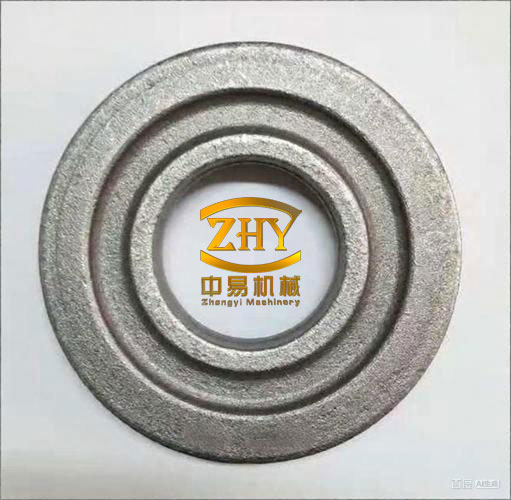
I have found that the forged gear blank produced by piercing and ring rolling has a geometry that is close to the final bevel gear blank. The process is especially suitable for annular and disc-like forged gear blanks. In my evaluation, the forged gear blank from the ring rolling route has no flash, a small piercing web, and a favorable fiber flow around the bore. This is important for the driven bevel gear, because the forged gear blank must later be machined into a spiral bevel gear with a precise mounting distance and a stable bore. I have inserted a representative image of the forged gear blank below to clarify the geometry under discussion.
Material Utilization and Dimensional Comparison
I begin with material utilization because it is the strongest argument for the ring rolling route. For any forged gear blank, I define the part weight as \(W_p\), the forging weight as \(W_f\), and the billet weight as \(W_b\). The material utilization based on the finished part is
$$
\eta_m = \frac{W_p}{W_b} \times 100\%.
$$
The forging yield, which measures how much of the billet becomes the forged gear blank before machining, is
$$
\eta_f = \frac{W_f}{W_b} \times 100\%.
$$
The flash and web loss ratio is
$$
r_{fw} = \frac{W_b – W_f}{W_b} \times 100\%.
$$
For the hammer route, I have found that flash and piercing web can exceed twenty percent of the forged gear blank weight. For the hot die forging press route, the flash and web are smaller than in hammer forging, but they are still significant. For the ring rolling route, there is no flash, and the piercing web is small enough that the material loss is much lower. In Table 2 I summarize the relative material performance of the three routes. The values are given as illustrative indices, with the hammer route normalized to 1.00 for billet weight and 1.00 for material loss.
| Material Index | Hammer Route | Hot Die Forging Press Route | Piercing and Ring Rolling Route |
|---|---|---|---|
| Flash and web loss | High, greater than 20% in many cases | Moderate, lower than hammer | Very low, no flash and small web |
| Billet weight index | 1.00 | 0.90 to 0.95 | 0.80 to 0.88 |
| Forging weight index | 1.00 | 1.00 | 1.00 |
| Material utilization index | 1.00 | 1.05 to 1.12 | 1.15 to 1.25 |
| Draft angle and fillet demand | Large | Moderate | Small |
| Machining allowance | Large | Moderate | Small to moderate |
The annual material saving from switching to ring rolling is
$$
\Delta M = N \left( W_{b,\text{hammer}} – W_{b,\text{ring}} \right),
$$
where \(N\) is the annual production volume. The annual cost saving from material alone is
$$
\Delta C_m = \Delta M \cdot p_m,
$$
where \(p_m\) is the material price per unit mass. If I take a representative case in which the ring rolling route saves a certain mass per forged gear blank, then at a high annual volume the saving becomes substantial. I have seen that for one automotive driven bevel gear forged gear blank, the saving per piece can be on the order of several tenths of a kilogram, and at an annual volume of one hundred thousand pieces the annual steel saving can reach tens of tonnes. This is a direct economic benefit that I cannot ignore.
I also compared the forged gear blank dimensions and tolerances. The hammer route generally requires larger draft angles, larger fillet radii, and larger machining allowances. The hot die forging press route gives tighter tolerances and smaller allowances, but it still produces flash and a piercing web. The ring rolling route gives a forged gear blank with a cleaner profile, smaller allowances, and better concentricity between the bore and the outer diameter. In my view, the dimensional quality of the ring rolled forged gear blank is closer to the hot die forging press route than to the hammer route, while the material yield is better than both. I have summarized the dimensional comparison in Table 3.
| Dimensional Feature | Hammer Route | Hot Die Forging Press Route | Piercing and Ring Rolling Route |
|---|---|---|---|
| Draft angle | Large | Moderate | Small or minimal |
| Fillet radius | Large | Moderate | Small |
| Machining allowance | Large | Small to moderate | Small |
| Flash | Present, often large | Present, smaller | None |
| Piercing web | Present, thick | Present, moderate | Present, thin |
| Bore concentricity | Moderate | Good | Very good |
| Surface quality after forging | Acceptable | Good | Good |
Equipment, Building, and Foundation Comparison
I have also evaluated the equipment weight, foundation depth, building height, bay area, crane capacity, and building cost. These factors are often underestimated when a plant first considers producing a forged gear blank. A large die forging hammer or a large hot die forging press requires a massive foundation, a high bay, and a heavy crane. The ring rolling route, by contrast, uses a more distributed set of smaller machines. I have expressed the equipment investment as
$$
I_{eq} = \sum_{i=1}^{n} W_i c_i,
$$
where \(W_i\) is the weight of machine \(i\) and \(c_i\) is its cost per unit weight. In my comparison, the ring rolling route has the lowest total equipment weight and the lowest total equipment investment, even though it may have one more machine in the cell. The reason is that the ring rolling machine, the piercing press, and the sizing press are much lighter than a large die forging press or a heavy steam-air hammer. I have summarized the relative equipment and infrastructure indices in Table 4.
| Infrastructure Item | Hammer Route | Hot Die Forging Press Route | Piercing and Ring Rolling Route |
|---|---|---|---|
| Main forming equipment weight | Very high | Very high | Moderate |
| Auxiliary equipment weight | Moderate | Moderate | Moderate to high |
| Total equipment weight index | 1.00 | 1.10 to 1.30 | 0.55 to 0.75 |
| Maximum equipment height above floor | High | High | Low to moderate |
| Required building height | High, for hammer rod removal | High, for tie rod assembly | Low to moderate |
| Crane capacity required | High | High | Low to moderate |
| Foundation depth | Deep, vibration isolation required | Deep, massive concrete block | Shallow to moderate |
| Cell area | Large | Large | Moderate |
| Building cost index | 1.00 | 1.05 to 1.20 | 0.60 to 0.80 |
The building investment can be approximated as
$$
I_{bld} = A c_A + V c_V + D c_D,
$$
where \(A\) is the floor area, \(c_A\) is the cost per unit area, \(V\) is the building volume, \(c_V\) is the cost per unit volume, \(D\) is the foundation depth, and \(c_D\) is the foundation cost factor. Because the ring rolling route reduces the bay height, the crane capacity, the foundation depth, and the cell area, it reduces \(I_{bld}\) directly. I have also considered the public utility requirements. The hammer route requires a boiler house, a gas station, and steam piping if it uses steam. The hot die forging press route requires a large electrical supply and sometimes a dedicated substation. The ring rolling route requires an induction heater, a hydraulic pump station for the piercing press, and a ring rolling machine drive. In my analysis, the ring rolling route has the lowest related investment in buildings and utilities. I have summarized the related investment items in Table 5.
| Related Investment | Hammer Route | Hot Die Forging Press Route | Piercing and Ring Rolling Route |
|---|---|---|---|
| Boiler house | Required for steam hammer | Not required | Not required |
| Gas station | Often required for flame furnace | Not usually required | Not required |
| Electrical substation | Moderate | Large | Moderate |
| Induction heating system | Not typical | Typical | Typical |
| Hydraulic system | Moderate | Large | Moderate |
| Compressed air system | Required | Required | Required |
| Water circulation | Required | Required | Required |
| Vibration isolation | Heavy | Moderate to heavy | Light |
Die and Tooling Comparison
I have examined the die weight, die price, die life, refurbishment cost, and die cost per forged gear blank. The die cost per piece is
$$
C_{die,u} = \frac{C_{die}}{L_{die}},
$$
where \(C_{die}\) is the total die cost and \(L_{die}\) is the die life in pieces. If the die can be refurbished \(n_r\) times, then
$$
C_{die,u} = \frac{C_{die} + n_r C_{ref}}{L_{die}(n_r + 1)},
$$
where \(C_{ref}\) is the refurbishment cost. In my comparison, the ring rolling route uses simpler dies and tooling. The piercing punches, the ring rolling rolls, and the sizing die are smaller and less expensive than a large hammer die or a large press die. The ring rolling tools also experience more favorable loading conditions because the deformation is incremental and mostly compressive. I have therefore found that the ring rolling route has a longer tool life and a lower die cost per forged gear blank. Table 6 summarizes the tooling comparison.
| Tooling Item | Hammer Route | Hot Die Forging Press Route | Piercing and Ring Rolling Route |
|---|---|---|---|
| Complete die set weight | Very high | High | Moderate |
| Die set price | Very high | High | Moderate |
| Die refurbishment count | Low to moderate | Moderate | Moderate to high |
| Die life | Low to moderate | Moderate | High |
| Die steel per tonne of forged gear blank | High | Moderate | Low |
| Die cost per piece | High | Moderate | Low |
| Tooling complexity | High | High | Moderate |
The die cost per piece has a direct effect on the unit cost of the forged gear blank. If I denote the unit cost of the forged gear blank as \(C_u\), then
$$
C_u = C_m + C_l + C_d + C_b + C_{die} + C_e + C_f + C_o – R_s,
$$
where \(C_m\) is material cost, \(C_l\) is labor cost, \(C_d\) is equipment depreciation, \(C_b\) is building depreciation, \(C_{die}\) is die cost per piece, \(C_e\) is electrical energy cost, \(C_f\) is fuel cost, \(C_o\) is overhead and auxiliary cost, and \(R_s\) is scrap recovery. In my analysis, the ring rolling route reduces \(C_m\), \(C_{die}\), \(C_e\), \(C_f\), and \(C_o\), while it may slightly increase \(C_l\) because the cell has more machines. However, the net effect is strongly favorable to the ring rolling route.
Productivity, Manpower, and Labor Content
I have evaluated the production capacity, crew size, and labor content of each route. The annual production capacity is
$$
P_a = P_h H_a \eta_a,
$$
where \(P_h\) is the hourly production rate, \(H_a\) is the annual working hours, and \(\eta_a\) is the availability factor. The labor productivity is
$$
L_p = \frac{P_a}{N_{crew}},
$$
where \(N_{crew}\) is the number of operators in the cell. The unit labor content is
$$
t_u = \frac{N_{crew} H_a}{P_a}.
$$
In my comparison, the hot die forging press route has the highest production rate and the lowest unit labor content when it operates at full capacity. The hammer route has a moderate production rate but requires more manual handling and has a worse working environment. The ring rolling route has a production rate comparable to the hammer route, and with mechanized handling it can exceed the hammer route. It requires more equipment in the cell, so the crew size may be slightly larger, but the labor content per forged gear blank is still competitive because the process is less dependent on highly skilled hammer operators. I have summarized the productivity and labor comparison in Table 7.
| Productivity and Labor Item | Hammer Route | Hot Die Forging Press Route | Piercing and Ring Rolling Route |
|---|---|---|---|
| Crew size | Moderate | Low to moderate | Moderate |
| Hourly production rate | Moderate | High | Moderate to high |
| Annual capacity | Moderate | High | Moderate to high |
| Unit labor content | High | Low | Moderate |
| Operator skill demand | High | Moderate | Moderate |
| Working environment | Poor, vibration and noise | Better | Best |
| Mechanization potential | Low to moderate | High | High |
I have also considered the cycle time of the ring rolling cell. The total cycle time is
$$
t_{cycle} = t_{load} + t_{upset} + t_{pierce} + t_{roll} + t_{size} + t_{unload}.
$$
If the handling operations are manual, \(t_{load}\), \(t_{unload}\), and the transfer between machines can dominate. If I introduce mechanized transfer and automatic sizing, the cycle time can be reduced substantially. In my judgment, the ring rolling route has the greatest potential for further automation because the motions are simple and repetitive. This is an important point for a forged gear blank that is produced in large volumes.
Fuel and Power Consumption
I have compared the fuel and power consumption of the three routes. The theoretical energy required to heat the billet is
$$
Q_h = \frac{m c_p (T_f – T_0)}{\eta_h},
$$
where \(m\) is the billet mass, \(c_p\) is the specific heat capacity, \(T_f\) is the final forging temperature, \(T_0\) is the initial temperature, and \(\eta_h\) is the heating efficiency. The mechanical energy for forming is approximately
$$
E_m = \int P(t) \, dt \approx P_{avg} t_{cycle},
$$
where \(P(t)\) is the instantaneous power and \(P_{avg}\) is the average power. The total unit energy is
$$
E_u = Q_h + E_m + E_{aux},
$$
where \(E_{aux}\) includes compressed air, hydraulic pumping, cooling water, and handling. In my comparison, the hammer route has the lowest heating efficiency if it uses a flame furnace, and it also requires steam for the hammer. The hot die forging press route usually uses induction heating, which has a higher heating efficiency, but the press itself has a large installed power. The ring rolling route also uses induction heating, and its forming machines are smaller, so the total connected load is lower. I have summarized the energy and fuel comparison in Table 8.
| Energy and Fuel Item | Hammer Route | Hot Die Forging Press Route | Piercing and Ring Rolling Route |
|---|---|---|---|
| Main heating method | Flame furnace | Induction heater | Induction heater |
| Heating efficiency | Low | Moderate to high | Moderate to high |
| Main forming energy | Steam or compressed air | Electric motor | Electric motor and hydraulic |
| Steam consumption | High if steam hammer | None | None |
| Compressed air consumption | Moderate | Moderate | Moderate |
| Cooling water consumption | Moderate | High | Moderate |
| Total energy per forged gear blank | High | Moderate | Low to moderate |
| Environmental impact | High emissions, noise, vibration | Moderate | Low |
The energy saving from the ring rolling route is
$$
\Delta E = E_{u,\text{hammer}} – E_{u,\text{ring}},
$$
and the annual energy cost saving is
$$
\Delta C_e = \Delta E \cdot N \cdot p_e,
$$
where \(p_e\) is the energy price per unit. I have found that the ring rolling route is especially attractive in regions where energy prices are high and where environmental regulations limit the use of coal-fired or gas-fired flame furnaces. The forged gear blank produced by ring rolling therefore has a lower embodied energy and a smaller environmental footprint.
Unit Cost Model and Economic Comparison
I have constructed a unit cost model for the forged gear blank. The total unit cost is the sum of material, labor, depreciation, building, die, energy, fuel, auxiliary, and overhead costs, minus scrap recovery. I have already given the general formula. For the three routes, I have used relative indices and have found that the ring rolling route has the lowest total unit cost in high-volume production. I have summarized the cost breakdown in Table 9. The values are relative, with the hammer route set to 100 for the total unit cost.
| Cost Element | Hammer Route | Hot Die Forging Press Route | Piercing and Ring Rolling Route |
|---|---|---|---|
| Material cost | 100 | 90 to 95 | 80 to 88 |
| Direct and indirect labor | 100 | 80 to 90 | 90 to 100 |
| Equipment depreciation | 100 | 110 to 130 | 60 to 80 |
| Building depreciation | 100 | 105 to 120 | 60 to 80 |
| Die and tooling | 100 | 90 to 100 | 60 to 80 |
| Electrical energy | 100 | 90 to 110 | 70 to 90 |
| Fuel and steam | 100 | 60 to 80 | 50 to 70 |
| Auxiliary and overhead | 100 | 100 to 110 | 80 to 95 |
| Scrap recovery credit | 100 | 100 to 105 | 105 to 115 |
| Total unit cost index | 100 | 95 to 105 | 75 to 88 |
I have also calculated the break-even volume between the hammer route and the ring rolling route. If the ring rolling route requires an additional investment \(I_{ring} – I_{hammer}\), and if the unit cost saving is \(C_{u,hammer} – C_{u,ring}\), then the break-even volume is
$$
N^* = \frac{I_{ring} – I_{hammer}}{C_{u,hammer} – C_{u,ring}}.
$$
In my analysis, the ring rolling route has a lower investment than the hammer route in many cases, so the break-even volume is not a barrier. Even if the ring rolling route requires some additional handling equipment, the unit cost saving is large enough that the break-even volume is low. The return on investment is
$$
ROI = \frac{(C_{u,hammer} – C_{u,ring}) N}{I_{ring}} \times 100\%.
$$
I have found that the ring rolling route gives a favorable return on investment because it reduces material cost, die cost, building cost, and energy cost simultaneously. This is the main reason why I consider it the best route for a forged gear blank that is produced in large quantities.
Quality and Process Capability
I have not limited my comparison to cost. I have also examined the quality of the forged gear blank. The ring rolling route produces a forged gear blank with a favorable grain flow around the bore. The incremental deformation in ring rolling tends to close internal porosity and to refine the microstructure. The absence of flash means that there is no flash-line defect on the rim. The small piercing web means that the web can be removed with less deformation and less risk of cracking. In my view, the ring rolled forged gear blank has good dimensional consistency and good surface quality. The hot die forging press route also produces good quality, but the large press and the flash require more trimming and more material. The hammer route can produce acceptable quality, but it depends more on the skill of the operator and on the condition of the hammer. I have summarized the quality comparison in Table 10.
| Quality Attribute | Hammer Route | Hot Die Forging Press Route | Piercing and Ring Rolling Route |
|---|---|---|---|
| Grain flow | Acceptable | Good | Very good around bore |
| Dimensional consistency | Moderate | High | High |
| Surface defects | Possible flash-line and scale | Low | Very low |
| Internal soundness | Moderate | Good | Good to very good |
| Machining allowance | Large | Moderate | Small |
| Process repeatability | Moderate | High | High |
| Operator dependence | High | Moderate | Low to moderate |
I have also considered the effect of the forged gear blank on the subsequent machining of the spiral bevel gear. A forged gear blank with a small allowance and a well-centered bore reduces the machining time and the risk of eccentricity. A forged gear blank with a favorable grain flow improves the fatigue life of the final gear. These benefits are difficult to quantify in a simple cost table, but they are real. In my assessment, the ring rolling route gives a forged gear blank that is well suited to high-volume production of driven bevel gears.
Domestic and International Adoption
I have reviewed the adoption of the piercing and ring rolling process for forged gear blanks in different regions. The process has been used for flywheel ring gears, tractor final drive gears, and automotive driven bevel gears. In some plants, the ring rolling cell is composed of an air hammer for upsetting, a friction press for piercing a stepped blind hole, a closed single-point press for piercing the web, a ring rolling machine for expanding and shaping, and a friction press for sizing. In other plants, the cell uses a hydraulic press for upsetting and piercing, an induction heater, a ring rolling machine, and a sizing press. I have summarized the typical configurations in Table 11.
| Application Area | Typical Cell Configuration | Product Type | Material Utilization | Production Rate |
|---|---|---|---|---|
| Automotive forged gear blank | Induction heater, hydraulic press, ring roller, sizing press | Driven bevel gear | High | Moderate to high |
| Tractor forged gear blank | Air hammer, piercing press, ring roller, correction hammer | Final drive gear and ring gear | High | Moderate |
| Flywheel ring gear forged gear blank | Air hammer, ring roller, friction press | Flywheel ring gear | High | Moderate |
| International automated line | Induction heater, automatic press, ring roller, sizing press, annealing furnace, shot blaster | Bevel gear blank and ring gear blank | Very high | High |
I have found that the international trend is toward more automated ring rolling lines for forged gear blanks. Some lines include automatic hot die forging presses, ring rolling machines, sizing presses, continuous annealing furnaces, and continuous shot blast machines. These lines produce forged gear blanks with large outer diameters and high material utilization. The surface allowance is small, and the production rate is high. In my judgment, the same principle applies to the automotive driven bevel gear forged gear blank: the more automated the cell, the lower the unit cost and the better the consistency.
Overall Assessment
I have compared the three routes across material utilization, equipment weight, foundation depth, building height, area, building cost, die weight, die price, die life, production capacity, crew size, labor content, fuel consumption, power consumption, and unit cost. The results are consistent. The hammer route is flexible but material-intensive, energy-intensive, and labor-intensive. The hot die forging press route gives good quality and high productivity, but it requires a very large press, a large foundation, a high bay, and a large investment. The piercing and ring rolling route gives the best material utilization, the lowest equipment weight, the shallowest foundation, the lowest building height, the lowest die cost, the lowest energy consumption, and the lowest unit cost in high-volume production. I have summarized the overall comparison in Table 12.
| Decision Factor | Hammer Route | Hot Die Forging Press Route | Piercing and Ring Rolling Route |
|---|---|---|---|
| Material utilization | Low | Moderate | High |
| Equipment investment | High | Very high | Moderate |
| Building and foundation investment | High | Very high | Moderate |
| Die cost | High | Moderate to high | Low |
| Energy consumption | High | Moderate | Low to moderate |
| Labor content | High | Low | Moderate |
| Unit cost | High | Moderate | Low |
| Quality | Acceptable | Good | Very good |
| Environmental performance | Poor | Moderate | Good |
| Suitability for high volume | Moderate | High | Very high |
I conclude that the piercing and ring rolling process is the best technical-economic route for producing a forged gear blank for an automotive rear axle driven bevel gear in large quantities. It is especially suitable for plants that do not have a large die forging press or a heavy die forging hammer. It also fits the principle of specialized cooperation, because the ring rolling cell can be dedicated to a family of annular forged gear blanks. The process has been improved over many years, and the latest ring rolling machines are more capable and more reliable. I have no doubt that the forged gear blank produced by this route will continue to replace hammer-forged and press-forged blanks in many applications.
In my final assessment, the most important formula is the unit cost comparison:
$$
C_{u,\text{ring}} < C_{u,\text{press}} < C_{u,\text{hammer}}
$$
for high-volume production of the forged gear blank. The second most important formula is the material utilization:
$$
\eta_{m,\text{ring}} > \eta_{m,\text{press}} > \eta_{m,\text{hammer}}.
$$
These two relationships summarize the technical-economic advantage of the ring rolling route. I have found that the forged gear blank is a product where process selection has a direct and measurable effect on cost, quality, and sustainability. The piercing and ring rolling route gives the best balance of these factors, and I recommend it for any plant that needs to produce a forged gear blank in large quantities without investing in a massive forging press or hammer line.