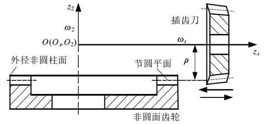
The machining basis of noncircular gear is the generating method. Firstly, the non-circular gear blank is processed, and the gear cutter is used to cut the gear. The modulus of the cutter is the same as that of the cylindrical gear meshed with the non-circular gear. As shown in Fig. 1, it is the schematic diagram of machining non-circular gear by the gear shaper cutter. The instantaneous angular velocity relationship between the cutter and the non-circular gear in the process of processing is as follows:

Where:
ρ – pitch radius of cutter (mm);
ψ s — angular velocity of tool (rad / s);
ι S2 — the ratio of angular velocity between cutter and non-circular gear.

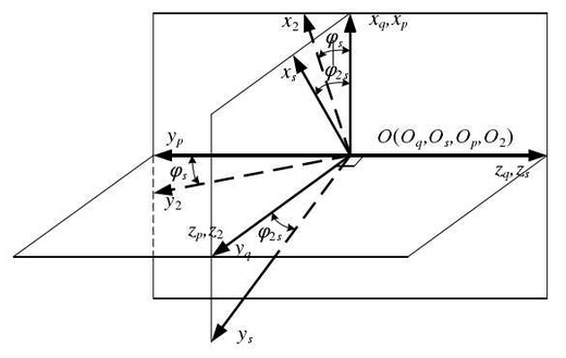
As shown in Figure 2, the fixed coordinate systems sq oqxqyqzq and SP opxpypzp fixed on the rack of gear shaper cutter and non-circular gear blank, and the dynamic coordinate systems SS osxsyszs and s2-o2x2y2z2 fixed on the surface of gear shaper cutter and non-circular gear respectively. The four coordinate systems have the same origin o (OO, OQ, Op, OS, O2), and the axes ZQ (ZS) are vertical and intersect with ZP (z2). The gear shaper cutter takes the coordinate axis ZQ (ZS) as the rotation axis, and the non-circular gear takes the ZP (Z2) axis as the rotation axis. ψ s is the turning angle of the tool, at this time, ψ 2S is the turning angle of the non-circular gear.

Through the coordinate transformation between the coordinate systems, the relationship between each coordinate system is obtained as follows:

In the process of machining, the angle of ψs is obtained as follows:

