
For decades, hypoid gears have been the cornerstone of power transmission in automotive drive axles and other critical applications, prized for their ability to transmit high torque between non-intersecting, non-parallel axes while enabling a lower overall driveline profile. The performance, efficiency, and noise-vibration-harshness (NVH) characteristics of a hypoid gear drive are fundamentally dictated by the geometry of its tooth surfaces. Hypoid gear tooth flank form is not arbitrary; it is the direct result of the manufacturing process and the kinematic settings of the gear-cutting machine. For most of the history of gear manufacturing, this form has been constrained by the mechanical limitations of traditional cradle-style generators. This paper explores a paradigm shift: moving from a process-oriented to a function-oriented design philosophy for hypoid gear tooth surfaces, enabled by advanced CNC manufacturing technology.
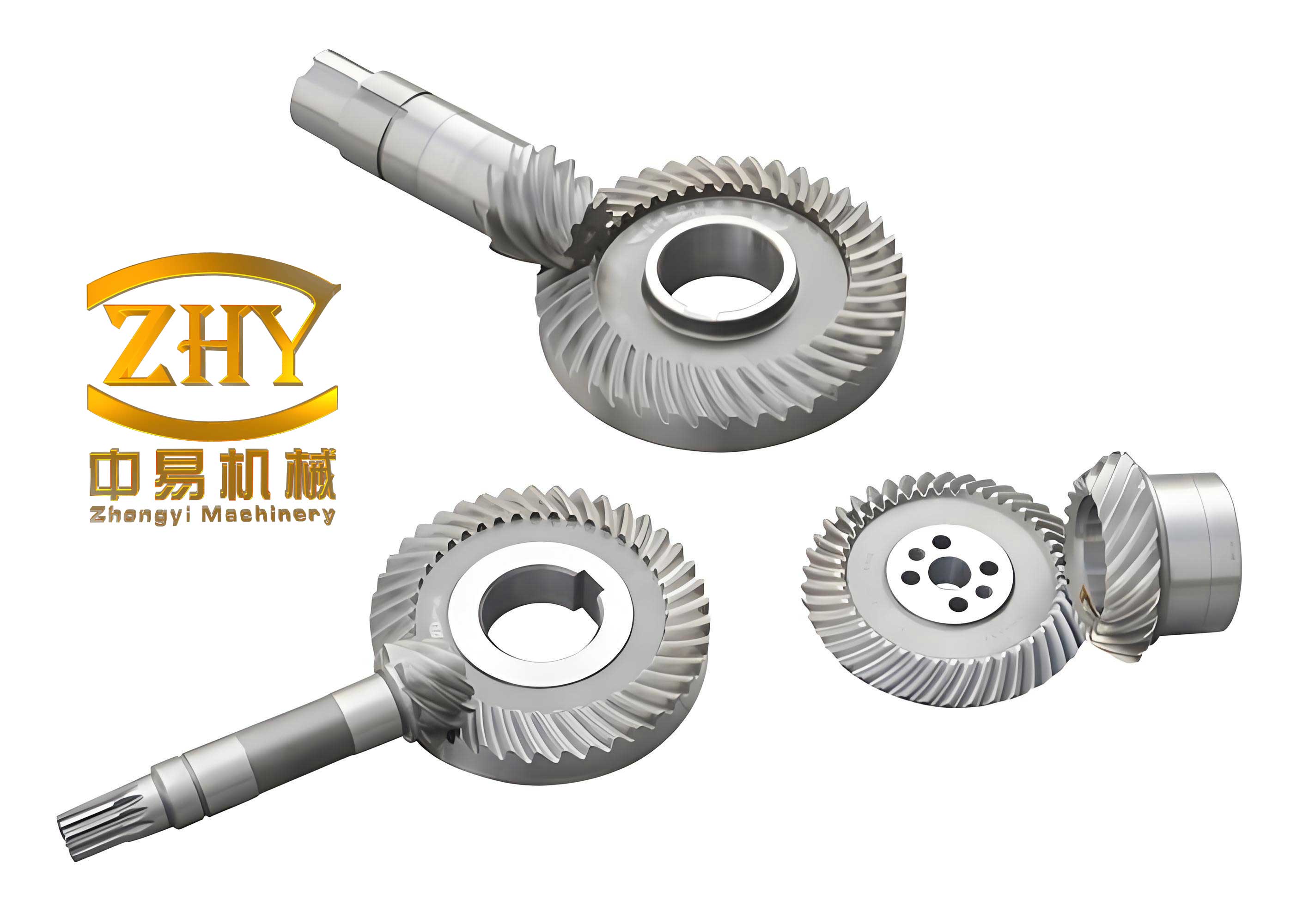
The Limitation of Traditional Design and Manufacturing
Conventional hypoid gear design is largely an iterative process of selecting “pre-defined” tooth surface forms. The designer chooses macro-geometric parameters such as number of teeth, module, pressure angle, spiral angle, and various correction coefficients. However, the detailed micro-geometry of the tooth flank—its local curvatures and their variation across the face width—is not directly designed. Instead, it is a passive outcome determined by the chosen machine tool settings (e.g., cutter radius, machine root angle, ratio of roll, sliding base settings) for a specific generator. The designer is essentially selecting from a limited library of tooth forms achievable by a specific mechanical machine. This creates several inherent limitations:
- Performance Ceiling: The optimal contact pattern, transmission error curve, and load distribution for a specific application might require a tooth surface that falls outside the library of forms producible by traditional machines.
- Error Sensitivity: Passively generated surfaces are not necessarily optimized for low sensitivity to assembly errors (misalignments) or manufacturing tolerances.
- Process Dependence: The design is inseparable from the manufacturing process. A design is valid only if it can be produced on a specific type of mechanical generator.
The advent of Computer Numerical Control (CNC) in gear manufacturing, particularly multi-axis CNC hypoid gear generators, was a revolutionary step. However, initial applications of this technology often merely replicated the kinematics of the old mechanical machines digitally—a process known as “cradle emulation.” While this improved flexibility and accuracy, it did not break free from the fundamental limitations of the traditional tooth form library. The machine’s potential was underutilized.
| Aspect | Traditional (Process-Oriented) Design | Function-Oriented (Active) Design |
|---|---|---|
| Starting Point | Machine tool settings and cutter geometry. | Desired performance parameters (Transmission Error, Contact Path, Contact Ellipse). |
| Design Variables | Machine adjustments (cradle angle, sliding base, etc.). | Local tooth surface parameters (coordinates, normals, curvatures) along a path. |
| Tooth Form | Pre-defined by machine kinematics. Limited choice. | Actively synthesized to meet performance goals. Form is unrestricted. |
| Manufacturing | Tied to specific mechanical generator types. | Directly mapped to CNC machine axes motions. |
| Primary Goal | To produce a gear that runs. | To produce a gear that runs optimally under defined conditions. |
Principles of Function-Oriented Tooth Surface Design
The core idea of function-oriented design is to treat the desired meshing performance as the input and solve for the tooth geometry that delivers it. This is an “inverse problem” compared to the traditional approach. We actively design the tooth surface by directly specifying its key characteristics along a predetermined path of contact.
The mathematical foundation is the theory of gearing and conjugate surfaces. Consider a gear pair consisting of Gear 1 (commonly the ring gear) and Gear 2 (the pinion). A fixed coordinate system $S(O-xyz)$ is established, with the $z$-axis along the axis of Gear 1 and the $z_1$-axis along the axis of Gear 2. The shaft angle is $\Sigma$, the offset is $E$, and the mounting distances of the gear apexes are $A_1$ and $A_2$.
The fundamental relationship for two surfaces $\Sigma^{(1)}$ and $\Sigma^{(2)}$ to be conjugate (i.e., to mesh properly) is given by the equation of meshing:
$$ \mathbf{n}^{(1)} \cdot \mathbf{v}^{(12)} = 0 $$
where $\mathbf{n}^{(1)}$ is the unit normal vector to surface $\Sigma^{(1)}$ at the contact point, and $\mathbf{v}^{(12)}$ is the relative velocity vector of Gear 1 with respect to Gear 2 at that point.
In active design, the process is typically as follows: one tooth surface (e.g., the ring gear $\Sigma^{(1)}$) is defined, often as a simple generated surface. The mating pinion surface $\Sigma^{(2)}$ is then synthesized so that it meshes with $\Sigma^{(1)}$ according to a pre-specified law of motion and possesses desired local contact properties.
The parameters that define the pinion surface $\Sigma^{(2)}$ along a designated contact path on $\Sigma^{(1)}$ are divided into first-order and second-order parameters:
- First-Order Parameters: These define the position and orientation of the surface. For each point on the contact path, we need the coordinates $(x^{(2)}, y^{(2)}, z^{(2)})$ and the unit normal vector components $(n_x^{(2)}, n_y^{(2)}, n_z^{(2)})$ in the pinion coordinate system $S_2$.
- Second-Order Parameters: These define the local curvature of the surface, which governs the shape and size of the contact ellipse. For each point, we need the principal curvatures $k_I^{(2)}$ and $k_{II}^{(2)}$ and their corresponding principal direction unit vectors $\mathbf{e}_I^{(2)}$ and $\mathbf{e}_{II}^{(2)}$.
The design variables become the performance targets: the transmission error function $\phi_2(\phi_1)$, the path of contact on the ring gear surface, and the dimensions of the instantaneous contact ellipse (e.g., its semi-major axis length $l_a$). From these, and using the conditions of continuous tangency and the law of conjugate motion, the necessary first and second-order parameters of the pinion surface along the contact path can be solved for uniquely. The surface at other points is naturally formed as the envelope of the cutter path during manufacturing, ensuring non-interference.
The governing equations for determining the pinion surface parameters from the desired mesh are derived from differential geometry and kinematics. They ensure point contact with the specified ellipse size. For a desired transmission error function $\phi_1 = F(\phi_2)$, the relative velocity is a function of this gearing law. The condition for a specified contact ellipse size relates the surface normal curvatures of both gears in the direction of the contact path tangent $\mathbf{t}$:
$$ \Delta k = k_t^{(1)} – k_t^{(2)} = \frac{1}{r_e} $$
where $r_e$ is related to the desired semi-major axis of the contact ellipse, and $k_t$ is the normal curvature in direction $\mathbf{t}$. This allows for direct calculation of the required pinion curvature $k_t^{(2)}$ at each point.
| Step | Action | Mathematical / Performance Goal |
|---|---|---|
| 1 | Define Gear 1 (Ring Gear) Surface | Typically a known, simple form (e.g., Gleason Coniflex®). Serves as the reference. |
| 2 | Specify Law of Motion | Define the functional relationship $\phi_1 = F(\phi_2)$, often a low-order polynomial to minimize TE excitation: $$ \phi_1 = \frac{N_2}{N_1}\phi_2 + C_2 \phi_2^2 + C_3 \phi_2^3 $$ |
| 3 | Define Contact Path on Gear 1 | Specify a curve on $\Sigma^{(1)}$, e.g., a straight line at an angle $\beta$ in the tooth profile-length plane: $f(R_1, H_1)=0$. |
| 4 | Specify Contact Ellipse Size | Define the semi-major axis $l_a$ or a function for it across the face width to control load intensity. |
| 5 | Solve for Pinion Surface Parameters | Use equations of meshing, conjugate condition, and ellipse size condition to compute $(x^{(2)}, y^{(2)}, z^{(2)})$, $\mathbf{n}^{(2)}$, $k_I^{(2)}$, $k_{II}^{(2)}$, $\mathbf{e}_I^{(2)}$, $\mathbf{e}_{II}^{(2)}$ for discrete points along the path. |
| 6 | Error Sensitivity Analysis | Analyze the sensitivity of the designed surface to misalignments. The second-order parameters can be tuned to minimize this sensitivity. |
Advanced CNC Manufacturing Technology for Actively Designed Surfaces
The beauty of the function-oriented design is that it liberates the tooth form from the constraints of mechanical generators. The resulting pinion surface is defined purely by its geometrical parameters, not by a set of machine settings. The challenge then becomes: how to manufacture this free-form surface? The answer lies in the flexible kinematics of a modern CNC hypoid gear grinder or cutter.
A three-axis CNC hypoid generator, as schematically shown, typically features two linear axes (X, Y) controlling the cutter head position and one rotary axis (A) controlling the workpiece rotation. There is no physical cradle, ratio gears, or eccentric mechanisms. The machine’s digital controller can synchronize the motion of these axes arbitrarily.
The manufacturing task is to find the continuous path of the cutter (modeled as a conical surface $\Sigma^{(c)}$) that will generate the designed pinion surface $\Sigma^{(2)}$ as its envelope. This requires determining the machine settings and the functional relationship between the axes. The key machine parameters for a given instant in the cutting process are:
- $A_{02}$: The mounting distance of the pinion work point.
- $B$: The machine root angle (workpiece tilt).
- $r_0$: The cutter point radius (or grinding wheel radius).
- $\alpha_0$: The cutter blade angle (positive for inside blade, negative for outside).
- $(x_{0c}, y_{0c}, z_{0c})$: The coordinates of the cutter center in the machine coordinate system $S_m(O-xyz)$.
For the cutter to generate the designed surface $\Sigma^{(2)}$, they must satisfy the conditions of a generating process, which are more stringent than simple contact. These are encapsulated in the Basic Equations of Gear Cutting:
- Position Identity: The cutter surface and the gear surface share the same contact point.
$$ \mathbf{r}^{(c)} = \mathbf{r}^{(2)} $$ - Normal Identity: Their unit normals are aligned at the contact point.
$$ \mathbf{n}^{(c)} = \mathbf{n}^{(2)} $$ - Equation of Meshing: The relative velocity must be perpendicular to the common normal.
$$ \mathbf{n}^{(2)} \cdot \mathbf{v}^{(c2)} = 0 $$ - Second-Order Contact Condition (for specified direction $\mathbf{t}$): To ensure the cutter generates the exact local curvature designed along the contact path, the normal curvatures and geodesic torsions must match in the direction $\mathbf{t}$ of the contact path.
$$ k_{t}^{(c)} = k_{t}^{(2)}, \quad \tau_{gt}^{(c)} = \tau_{gt}^{(2)} $$
This condition is crucial for transferring the actively designed second-order parameters to the actual workpiece.
In these equations, $\mathbf{v}^{(c2)}$ is the relative velocity of the cutter relative to the workpiece. For a CNC machine with a rotating cutter head and a translating cradle-center point, this velocity is a function of the workpiece rotation $\omega_2$ and the time derivatives of the cutter center coordinates $\dot{x}_{0c}$ and $\dot{y}_{0c}$:
$$ \mathbf{v}^{(c2)} = \begin{bmatrix} -\dot{x}_{0c} \cos B + \dot{y}_{0c} \sin B \\ -\dot{x}_{0c} \sin B – \dot{y}_{0c} \cos B \\ 0 \end{bmatrix} + \boldsymbol{\omega}_2 \times \mathbf{r}^{(2)} $$
where $\boldsymbol{\omega}_2 = [0, -\omega_2 \sin B, \omega_2 \cos B]^T$.
Given the first and second-order parameters of the designed pinion surface $\Sigma^{(2)}$ along the contact path, the system of equations (1) through (4) can be solved. This yields, for each angular position $\phi_2$ of the pinion, the required instantaneous values of:
- The cutter location $(x_{0c}, y_{0c}, z_{0c})$.
- The first derivatives $(\dot{x}_{0c}, \dot{y}_{0c})$ related to the feed rate.
- The second derivatives $(\ddot{x}_{0c}, \ddot{y}_{0c})$, which are necessary for ensuring smooth, jerk-free motion and accurate curvature generation.
The machine root angle $B$, offset $A_{02}$, cutter radius $r_0$, and blade angle $\alpha_0$ are typically treated as constants for a given gear and are determined from global constraints like root clearance, face width, and overall gear geometry.
Motion Function Synthesis for the CNC Machine
The solution process provides discrete data points: for pinion rotation angles $\phi_2^{(i)}$, we have corresponding $x_{0c}^{(i)}, y_{0c}^{(i)}, \dot{x}_{0c}^{(i)}, \dot{y}_{0c}^{(i)}, \ddot{x}_{0c}^{(i)}, \ddot{y}_{0c}^{(i)}$. To command the CNC machine, we need continuous, differentiable motion functions $x_{0c}(\phi_2)$ and $y_{0c}(\phi_2)$. A highly effective method is to use fifth-order polynomials defined over segments of the rotation range.
For a segment $i$ between $\phi_2^{(i,1)}$ and $\phi_2^{(i,2)}$, we define:
$$ x_{0c}^{(i)}(\phi_2) = a_{i0} + a_{i1}\phi_2 + a_{i2}\phi_2^2 + a_{i3}\phi_2^3 + a_{i4}\phi_2^4 + a_{i5}\phi_2^5 $$
$$ y_{0c}^{(i)}(\phi_2) = b_{i0} + b_{i1}\phi_2 + b_{i2}\phi_2^2 + b_{i3}\phi_2^3 + b_{i4}\phi_2^4 + b_{i5}\phi_2^5 $$
The six coefficients $a_{i0}$ to $a_{i5}$ are uniquely determined by imposing the boundary conditions at the start and end of the segment: the known values of $x_{0c}$, $\dot{x}_{0c}$, and $\ddot{x}_{0c}$. The same is done for the $b$-coefficients using the $y_{0c}$ data. This ensures $C^2$ continuity (position, velocity, and acceleration) across segment boundaries, resulting in a smooth machine motion essential for high-quality surface finish.
| Parameter | Symbol | Typical Value / Description |
|---|---|---|
| Workpiece Mounting Distance | $A_{02}$ | Determined from gear blank design (e.g., 0 mm if work point at origin). |
| Machine Root Angle | $B$ | Calculated from gear geometry (e.g., 9.1358°). |
| Cutter Point Radius | $r_0$ | Selected based on gear size and slot width (e.g., 98.553 mm). |
| Cutter Blade Angle | $\alpha_0$ | Chosen for desired pressure angle; negative for outside blades (e.g., -19.5°). |
| Static Cutter Offset | $z_{0c}$ | Establishes the basic distance from cutter axis to gear axis (e.g., 0.508 m). |
| Motion Functions | $x_{0c}(\phi_2)$, $y_{0c}(\phi_2)$ | 5th-order polynomials, coefficients calculated per segment. |
Calculation Example and Implementation
Consider a hypoid gear pair for an automotive axle with the following data:
- Shaft Angle: $\Sigma = 90^\circ$
- Offset: $E = 35$ mm
- Gear Ratio: 37:6
- Design Goals for Drive Side Pinion:
- Transmission Error: A parabolic function to minimize excitation: $$ \phi_1 = \frac{6}{37}\phi_2 + 0.02\phi_2^2 $$
for $\phi_2$ in a normalized range. - Contact Path on Ring Gear: A straight line at a $60^\circ$ angle across the tooth face in the axial section plane.
- Contact Ellipse: A semi-major axis length $l_a$ maintained between 16-18 mm across the face width.
- Transmission Error: A parabolic function to minimize excitation: $$ \phi_1 = \frac{6}{37}\phi_2 + 0.02\phi_2^2 $$
The function-oriented design process yields the first and second-order parameters for the pinion tooth flank. Subsequent application of the cutting equations, with constraints for proper root form and no undercutting, produces the following constant machine parameters and motion function coefficients for one segment of the cutting cycle.
The constant parameters for the drive side are: $A_{02} = 0$ mm, $B = 9.1358^\circ$, $z_{0c} = 0.508$ m, $\alpha_0 = -19.5^\circ$, $r_0 = 98.553$ mm.
The motion functions for the cutter center for a segment spanning $\phi_2$ from $-1.40$ to $-0.05784$ (normalized rotation) are defined by the following polynomial coefficients. A second segment would have its own set of coefficients for the remainder of the stroke.
| Coefficient | Value for $x_{0c}(\phi_2)$ | Value for $y_{0c}(\phi_2)$ |
|---|---|---|
| $a_0$ / $b_0$ | 72.887532 | -62.222935 |
| $a_1$ / $b_1$ | 16.362120 | 7.142578 |
| $a_2$ / $b_2$ | -0.373876 | 1.102186 |
| $a_3$ / $b_3$ | -0.102198 | 0.05680 |
| $a_4$ / $b_4$ | -0.015530 | -0.02593 |
| $a_5$ / $b_5$ | 0.000460 | -0.00711 |
These coefficients, along with the constant settings, form the complete digital instruction set for the CNC hypoid gear generator. The machine controller interpolates the polynomial functions in real-time, synchronizing the X, Y, and A axes to physically create the actively designed tooth surface on the pinion blank. The same methodology is applied separately to design and generate the coast side flank of the hypoid gear pinion, often with different performance targets (e.g., a different contact path).
Conclusion and Future Outlook
The function-oriented design and direct CNC manufacturing of hypoid gear tooth surfaces represent a significant advancement in gear technology. This methodology fundamentally shifts the focus from the limitations of the machine tool to the requirements of the final application. By directly specifying key meshing performance parameters—such as a low-excitation transmission error function, a stable and favorably oriented contact path, and a controlled contact ellipse size—engineers can synthesize an optimal tooth flank geometry. This actively designed surface is free from the constraints imposed by the kinematics of traditional mechanical generators.
Critically, this theoretically optimal surface is not just a digital model. The flexibility of modern multi-axis CNC hypoid gear cutting and grinding machines makes its production not only possible but practical. By solving the basic equations of gear cutting for the designed surface, the required motions of the CNC axes (typically just three: two linear and one rotary) are determined. These motions are accurately described by high-order polynomial functions, ensuring smooth generation and faithful reproduction of the designed local curvatures. The process seamlessly integrates design and manufacturing, eliminating the need for the intermediary step of converting a design into a set of archaic “machine settings.”
The benefits are substantial: the potential for significantly improved gear performance in terms of noise, vibration, efficiency, and load capacity; reduced sensitivity to assembly misalignments; and a streamlined, digital workflow from performance target to finished part. As computational power increases and CNC machine tools become even more precise and widespread, this function-oriented approach is poised to become the standard for designing and manufacturing high-performance hypoid gears, pushing the boundaries of what is possible in power transmission systems.